
- All
- Product Name
- Product Keyword
- Product Model
- Product Summary
- Product Description
- Multi Field Search
English
Views: 0 Author: Site Editor Publish Time: 2026-09-04 Origin: Site


Manual degating creates a severe operational bottleneck in high-volume injection molding environments. Operators wielding hand nippers struggle to maintain pace with rapid machine cycles, introducing hidden costs that erode per-part margins. Inconsistent gate vestige requires secondary finishing operations, while scrap rates escalate due to accidental part damage during sprue removal. Furthermore, repetitive hand motions expose workers to severe ergonomic injuries, driving up workers' compensation claims and labor expenses. Transitioning to a dedicated Gate Cutting Machine eliminates these inefficiencies. It represents a necessary step for scaling production and standardizing quality. Implementing mechanical cutting solutions enables fully automated, lights-out work cells. You achieve consistent cycle times while reallocating human operators to higher-value quality inspection tasks.
Automating the degating process with a gate cutting machine standardizes flush cuts, reducing secondary finishing operations and lowering scrap rates.
Selecting the right machine requires matching cutting force, actuation method, and blade geometry to the specific polymer’s tensile strength and brittleness (e.g., glass-filled vs. unfilled resins).
Integration options range from standalone pneumatic benchtop units to fully integrated End-of-Arm Tooling (EOAT) robotic cutters, each offering distinct ROI timelines.
Mitigating implementation risks requires upfront material cut-testing, selecting the correct blade metallurgy, and establishing strict preventative maintenance schedules.
Evaluating a degating upgrade requires establishing clear baseline metrics. You must measure cycle time reduction, labor reallocation potential, and vestige tolerance limits. Success depends on moving away from manual variability. Injection molders cannot scale operations effectively when tied to the speed of human hands. Establishing strict success criteria allows engineering teams to justify the capital expenditure. You must audit current scrap rates directly attributed to poor gate removal. Track the exact time operators spend clipping parts versus performing actual quality checks.
Cycle Time Impact: Measure the exact seconds added to the overall cycle by manual gate removal.
Scrap Rate Audit: Quantify the percentage of parts rejected specifically due to gouging, stress whitening, or excessive vestige.
Labor Allocation: Calculate the man-hours spent exclusively on clipping sprues per shift.
Ergonomic Incident Rate: Review safety logs for hand, wrist, and forearm complaints over the past 24 months.
Dedicating operators to manual sprue cutting drains financial resources. Human hands cannot match the speed or consistency of mechanical actuation. Labor costs compound when operators must inspect and rework uneven cuts. A manual clipping process often adds three to five seconds per part. Over a standard production shift, these seconds accumulate into hours of lost machine time. When running multi-cavity molds, the operator falls behind the press, forcing the molding machine to wait and disrupting the thermal rhythm of the mold.
Repetitive Strain Injuries (RSI) present a massive liability on the shop floor. Using manual hand nippers thousands of times per shift damages tendons and joints. Carpal tunnel syndrome and tendonitis run rampant in manual finishing departments. Workers' compensation claims arising from these injuries severely impact operational budgets and drive up insurance premiums. Automating the cut removes the ergonomic hazard entirely. It protects your workforce, stabilizes your labor expenditures, and keeps the production floor compliant with occupational health standards.
Mechanical gate cutting eliminates human error from the finishing process. It ensures a repeatable, flush cut that meets strict dimensional tolerances. Hand tools often leave jagged edges or pull material from the part surface, especially when operators experience fatigue late in their shift. A rigid cutting setup maintains exact blade positioning for every cycle. This precision drastically reduces scrap rates caused by over-cutting into the A-surface or under-cutting and leaving sharp protrusions.
Manual removal often stresses the molded part, creating invisible micro-fractures. Operators tend to twist or pull the sprue while clipping, which transfers mechanical stress directly into the gate area. Automated systems apply focused, instantaneous force. They sever the gate cleanly without transferring stress to the surrounding polymer structure. Achieving a flush vestige of less than 0.5 millimeters consistently requires mechanical intervention. Human operators simply suffer from fatigue, leading to variable cut angles and unacceptable cosmetic defects that fail quality control inspections.
Injection molders can choose from various equipment architectures. Selection depends on automation level, actuation type, and specific application requirements. Understanding the distinct categories ensures you deploy the correct technology for your specific production cell and part geometry.
These are stationary pneumatic units mounted directly to workstations or conveyor outfeeds. Operators trigger them via foot pedals or simple optical sensors. They suit semi-automated cells and medium-volume production runs where full robotic extraction is not feasible. Benchtop units excel in applications requiring two-handed part manipulation by an operator. They provide immense cutting force while keeping the operator's hands free to position complex geometries against custom nesting fixtures.
These units often feature adjustable mounting brackets. This allows technicians to angle the cutting head to match the specific geometry of the incoming part. Benchtop systems bridge the gap between manual hand tools and fully robotic integration. They require minimal programming and run off standard shop air, making them highly deployable across different molding machines as production schedules shift.
These systems mount nippers directly to Cartesian linear robots or 6-axis articulated arms. They represent the peak of injection molding automation. EOAT cutters suit high-volume manufacturing environments. The robot removes the sprue before dropping or placing the part on a conveyor. This sequence ensures zero drop-damage and maintains strict part orientation for downstream assembly or packaging.
Integrating a Gate Cutting Machine directly onto the robot arm maximizes floor space efficiency. The cutting action happens in mid-air or directly above a scrap chute. This eliminates the need for secondary handling stations. EOAT integration requires lightweight nipper bodies to prevent overloading the robot's payload capacity. Engineers must balance the weight of the pneumatic cylinder and blades against the robot's dynamic movement capabilities to prevent vibration during the cut.
Pneumatic cutters remain the industry standard. They offer high instantaneous cutting force and exceptional durability in rugged environments. Compressed air provides rapid actuation necessary for fast cycle times. Most pneumatic systems operate efficiently between 60 and 90 PSI. They utilize simple directional control valves and require very little maintenance beyond occasional seal replacement.
Electric or servo-driven cutters offer different advantages. They feature programmable stroke control and precision speed adjustments. Electric models eliminate compressed air requirements, making them ideal for facilities lacking robust pneumatic infrastructure. Servo-driven units allow engineers to program the exact closing speed of the jaws. This controlled shearing action proves highly beneficial for processing delicate or highly stressed polymers where a sudden pneumatic snap might cause the gate to shatter.
Actuation Type | Primary Advantage | Ideal Application Environment | Maintenance Requirement |
|---|---|---|---|
Pneumatic (Standard) | High instantaneous force, low cost | Rugged shop floors, high-speed cells | Low (Seal checks, air lubrication) |
Pneumatic (Slide) | Flush cutting on flat surfaces | Cosmetic parts requiring zero vestige | Medium (Linear bearing lubrication) |
Electric (Solenoid) | No compressed air required | Cleanrooms, light-duty cutting | Low (Electrical contact checks) |
Electric (Servo) | Programmable jaw speed and position | Brittle resins, high-precision medical | High (Software updates, motor tuning) |
Standard nippers feature jaws that open and close in a fixed position. They work perfectly for standard sprues and easily accessible gates where a slight vestige is acceptable. The mechanical action is simple, reliable, and highly repeatable. However, because the blades close in an arc, they can sometimes push the part away slightly during the cut if not properly fixtured.
Slide nippers operate differently. The entire cutting unit physically slides forward flush against the molded part before actuating. This sliding mechanism proves essential for achieving zero-vestige requirements on flat surfaces. It prevents the blades from dragging across the part during extraction. Slide nippers utilize precision linear bearings to ensure smooth, repeatable forward motion. The stroke length adjusts to accommodate different mold designs and part clearances, allowing the blades to reach into tight pockets before snapping shut.
Cold cutting utilizes standard ambient temperature blades. It works effectively for most flexible and semi-rigid thermoplastics like polypropylene, polyethylene, and standard ABS. The mechanical shear force easily overcomes the tensile strength of these materials without causing structural damage.
Heated cutting systems utilize thermal nippers designed specifically for brittle materials. Cutting acrylic (PMMA), polystyrene (PS), or polycarbonate (PC) cold often causes micro-cracking, crazing, and stress whitening at the gate location. Heated blades melt through the gate slightly as they cut. This localized heat prevents mechanical shearing forces from fracturing the delicate polymer structure. Heated systems require dedicated temperature controllers. Technicians must calibrate the blade temperature to match the specific melt point of the resin being processed, usually ranging from 60°C to 150°C.
Evaluating a machine requires a strict technical framework. You must align equipment specifications with your specific injection molding requirements. Guesswork during the specification phase leads to inadequate cutting force, premature equipment failure, and unacceptable part quality.
Calculating the required cutting force is a critical first step. Force depends entirely on the gate's cross-sectional area and the polymer's hardness and tensile strength. Soft elastomers (TPE/TPU) require minimal force, while rigid engineering resins (PEEK, Glass-filled Nylon) demand significant power. Engineers calculate the required force by multiplying the cross-sectional area of the gate by the tensile yield strength of the specific polymer.
You must oversize the cutting force by 20 to 30 percent during specification. This buffer accounts for natural blade dulling over time. Operating a cutter at its absolute maximum capacity accelerates wear and leads to incomplete cuts as the blade edge degrades. Engineers must consult material data sheets to determine the exact tensile yield strength before sizing the pneumatic cylinders. Failing to oversize the cylinder results in the blades stalling halfway through the gate, requiring manual intervention to clear the jam.
Blade profiles directly impact vestige height and final part finish. Flat blades provide the most flush cut on flat surfaces, leaving virtually no protrusion. Single-bevel and double-bevel designs offer different shearing dynamics for angular gates or thick sprues. Metallurgy dictates blade lifespan. High-Speed Steel (HSS) handles standard unfilled resins effectively. Highly abrasive materials, like glass-filled nylons, require brazed Carbide-tipped blades to prevent rapid edge deterioration.
Flat Blades: Ideal for flat surfaces requiring zero vestige. The flat side rests directly against the part.
Standard Bevel: Provides robust cutting edges for thick sprues. The angled edge pushes material away from the cut.
Angled Blades: Navigates tight clearances inside complex mold cavities. Available in 15, 45, and 90-degree offsets.
Carbide Inserts: Mandatory for any resin containing glass fiber, carbon fiber, or mineral fillers to prevent the edge from rounding over in a matter of days.
Mold design and gate location dictate physical clearance requirements. Sub-gates, edge gates, and cashew gates all present unique access challenges. The machine's jaws must navigate the mold space or EOAT envelope without colliding with ejector pins, core pulls, or the molded part itself. 3D CAD modeling of the cutting sequence ensures the nipper body clears all obstacles before actuation.
The actuation and recovery speed of the cutter must align with the injection molding machine. Evaluate how quickly the blades close and reset. Ensure the cutting operation does not become the new limiting factor in your cycle time. Rapid exhaust valves on pneumatic cylinders help achieve millisecond response times, allowing the jaws to snap shut and open instantly.
For EOAT applications, calculate the robot travel time required to position the part within the nipper jaws. Optimize the robot path to execute the cut during the mold cooling phase whenever possible. Parallel processing ensures the degating step adds zero seconds to the overall manufacturing cycle. The robot extracts the part, moves to a safe zone, and the Gate Cutting Machine severs the sprue while the injection molding machine is already injecting the next shot.
Installing new equipment requires analyzing logistical realities on the factory floor. Proper integration ensures maximum return on your automation investment. You must look beyond the machine itself and evaluate the entire production cell, including communication protocols and physical space constraints.
Integrating a cutter into an existing cell requires careful planning. You must interface the unit with existing PLCs and IMM controllers. Safety interlocks must comply with standard communication protocols like Euromap 67 or Euromap 73 standards. Proper handshaking between the molding machine, robot, and cutter prevents catastrophic collisions. For example, the press must not close if the robot is still in the mold area performing a cut.
Signal delays must be minimized to maintain rapid sequence execution. Hardwiring sensor feedback directly into the robot controller ensures the arm only moves once the cut is fully verified. Magnetic reed switches on the pneumatic cylinders confirm the jaws have fully closed and fully opened, sending a 24V DC signal back to the PLC to trigger the next step in the automation sequence.
Standard pneumatic exhaust poses severe challenges in ISO-certified cleanrooms. Exhaust air disturbs particulates, blows dust across sterile surfaces, and compromises cleanroom integrity. Medical device manufacturing requires strict contamination control. Transitioning to electric gate cutters eliminates exhaust entirely, making them inherently cleanroom friendly.
Alternatively, you can utilize piped-exhaust pneumatic systems. These systems capture the expelled air from the directional valves and route it through tubing outside the cleanroom environment. This maintains compliance while leveraging the high force and low cost of pneumatic power. ISO Class 7 and Class 8 environments mandate strict adherence to these exhaust management protocols to pass certification audits.
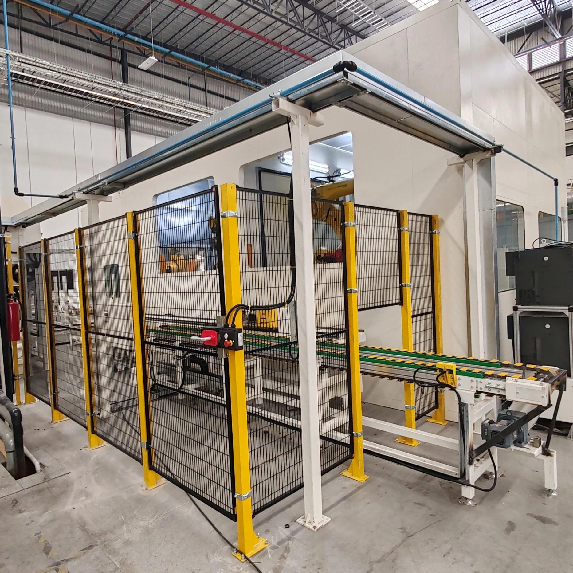
Factory floor space represents premium real estate. Standalone automated degating stations require dedicated square footage next to the press. They often necessitate additional safety fencing, light curtains, and part conveyors to move the finished goods away from the cutting zone. This expands the footprint of the molding cell significantly.
EOAT solutions utilize the existing robot envelope. They perform the cut above the press or directly over the drop zone. This integration saves valuable floor space and simplifies the overall cell layout. Maximizing vertical space above the injection molding machine keeps the shop floor clear for material handling equipment, forklifts, and operator movement.
Calculating the payback period requires tracking specific operational metrics. Use this straightforward framework to evaluate the investment: (Labor Savings + Scrap Reduction + Increased Throughput) / (Machine Cost + Integration Cost + Maintenance). Factor in the elimination of secondary finishing tools and the reduction in workers' compensation premiums.
A properly sized system typically demonstrates a rapid payback period in high-volume applications, often under six months. Capturing the cost of recovered scrap material further accelerates the return on investment. When you eliminate manual gouging, you stop throwing away perfectly molded parts, directly increasing your yield per shift.
Injection molders face common pitfalls post-purchase. Proactive planning prevents these issues from disrupting production schedules. Addressing risks before installation guarantees a smooth transition to automated degating and protects your capital investment.
Dull blades represent a massive operational risk. They lead to stressed parts, plastic stringing, or incomplete cuts that jam downstream automation. When a blade fails to cut completely, the robot may attempt to drop the part, but the attached sprue causes it to hang, triggering a cell fault and stopping production.
Mitigate this risk by establishing cycle-count-based preventative maintenance schedules. Utilize stroke-counters on the pneumatic cylinders or track cycles through the PLC to monitor exact usage. Maintain an on-site inventory of replacement blades to prevent catastrophic downtime. Swap blades proactively before cut quality degrades past acceptable tolerance limits. Waiting for a blade to fail during a production run guarantees scrapped parts and wasted machine hours.
Mechanical shearing forces easily cause subsurface cracks in clear or brittle resins like polycarbonate or acrylic. These micro-cracks often remain invisible to the naked eye until the part fails under load in the field, leading to costly product recalls.
Mandate pre-purchase cut-testing with actual molded samples. Send your specific polymer to the equipment manufacturer for validation. Utilize heated blades to melt through the stress zone. Adjust cutting speed and cylinder pressure to find the optimal shearing dynamic for sensitive materials. Inspecting test cuts under polarized light reveals hidden stress concentrations before full-scale production begins, allowing engineers to tweak the cutting parameters.
High-force pneumatic and electric cutters present severe pinch-point and amputation hazards. A cylinder capable of generating 2,000 Newtons of force will easily crush bone. Operator safety must remain the absolute priority during implementation and daily operation.
Ensure strict compliance with OSHA and ISO safety standards. Utilize light curtains to detect operator presence near the cutting zone, instantly dumping air pressure if the beam is broken. Implement two-hand anti-tie-down relays for benchtop units to ensure both hands remain clear during actuation. Install physical Lexan guarding to prevent accidental contact with moving jaws. Proper safety protocols protect your workforce and shield your facility from regulatory fines.
Transitioning to a dedicated cutting system is a mandatory evolution for modern molders. It empowers facilities to scale volume, protect margins, and maintain strict quality control. Relying on manual hand tools restricts growth and introduces unnecessary variability. We recommend pneumatic benchtop units for high-mix, low-volume facilities requiring operator flexibility. EOAT robotic cutters serve best in low-mix, high-volume, or cleanroom operations where speed and consistency reign supreme.
Take these immediate next steps to begin your upgrade:
Isolate your highest-volume or highest-scrap part to serve as your baseline test case.
Calculate the exact cutting force required based on the gate dimensions and polymer tensile strength.
Send sample parts and runners to equipment manufacturers for proof-of-concept cut testing.
Audit your existing robotic cells to determine payload capacity for EOAT integration.
Establish a standardized blade replacement schedule based on projected cycle counts.
A: It is specialized equipment used to cleanly sever the sprue or gate from a molded plastic part. It replaces manual hand tools, standardizes cut quality, and eliminates the ergonomic risks associated with repetitive manual clipping.
A: Force depends entirely on the cross-sectional area of the gate and the tensile strength of the specific polymer. Required force typically ranges from 100 Newtons for soft plastics to over 2,000 Newtons for thick, rigid engineering resins.
A: Specify heated usage for brittle materials like acrylic, polystyrene, or polycarbonate. Cold shearing these plastics often causes stress whitening, crazing, or micro-fracturing. Heated blades melt through the material slightly, preventing mechanical stress transfer.
A: Lifespan varies wildly based on the material being processed. Cutting unfilled resins may allow hundreds of thousands of cycles before dulling. Conversely, highly glass-filled resins may dull standard High-Speed Steel blades in days, requiring specialized carbide inserts.
A: Yes. End-of-Arm Tooling (EOAT) nippers are designed specifically for this purpose. They require standard pneumatic lines or electrical connections and utilize simple I/O integration with the existing robot controller to synchronize the cutting sequence.
A: A sprue picker is a simple robot that physically removes the entire runner system from the mold area. A gate cutter is the specific tool that physically severs the connection between that runner or sprue and the final molded part.
A: Yes, provided you select the correct configuration. Standard pneumatic cutters exhaust air that can disturb particulates. However, electric cutters or pneumatic units fitted with ducted exhausts are fully cleanroom compatible and prevent environmental contamination.


