
- All
- Product Name
- Product Keyword
- Product Model
- Product Summary
- Product Description
- Multi Field Search
English
Views: 0 Author: Site Editor Publish Time: 2026-09-05 Origin: Site


The precision of a gate in injection molding dictates the structural integrity and cosmetic finish of the final part. It also controls the efficiency of the entire production cycle. Miscalculated gate sizes lead to high shear rates, short shots, or excessive cycle times. Oversized or improperly placed gates create post-processing bottlenecks on the shop floor. These bottlenecks drive up manual labor costs and increase the risk of part damage during degating.
Moving from theoretical mold design to production reality requires a dual approach. You must accurately calculate gate dimensions based on polymer rheology, shot size, and part geometry. You must also align those dimensions with automated post-processing solutions. Integrating a proper Gate Cutting Machine ensures scalable manufacturing and eliminates manual trimming inconsistencies.
Formulaic Precision: Gate dimensions (depth, width, and length) must be calculated using specific ratios tied to the part's nominal wall thickness, total shot volume, and the polymer’s viscosity index.
Flow vs. Freeze Trade-off: The gate must be large enough to pack out the part without excessive shear, yet small enough to freeze off quickly and minimize cycle time.
System-Wide Alignment: Gate sizing cannot be done in isolation; it must account for machine injection capacity, runner weight, and multi-cavity layouts.
Post-Processing Dependency: The calculated cross-sectional area of the gate directly determines the required cutting force for removal, dictating the specifications of post-processing equipment.
Automation ROI: Transitioning from manual trimming to a dedicated gate cutting machine is justified when gate thickness, material hardness, and production volumes exceed manual ergonomic thresholds.
An optimal gate serves three primary functions during the injection molding process. First, it controls the polymer flow direction into the cavity. Second, it manages the shear rate to prevent material degradation. Third, it ensures proper volumetric packing before freeze-off occurs. If the gate fails at any of these tasks, the molded part will suffer from defects. Engineers must balance these requirements carefully on the shop floor. A gate that fills the cavity quickly might freeze too slowly, extending the cycle time. A gate that freezes quickly might restrict flow and cause short shots or severe sink marks in thick wall sections.
Gate cross-sectional area directly influences polymer velocity. When plastic melt forces its way through a narrow gate, its velocity spikes. This rapid movement generates friction, known as shear heating. Moderate shear heating helps reduce viscosity and aids cavity filling. However, excessive shear degrades the polymer chains. Material degradation leads to brittle parts, discoloration, and splay marks. Different polymers have different shear rate limits that you must respect during gate sizing.
Maximum Allowable Shear Rates for Common Polymers | ||
Polymer Type | Maximum Shear Rate (1/s) | Risk of Exceeding Limit |
|---|---|---|
PVC (Rigid) | 20,000 | Severe burning, corrosive off-gassing |
Polycarbonate (PC) | 40,000 | Chain scission, loss of impact strength |
ABS | 50,000 | Surface splay, color shift |
Polypropylene (PP) | 100,000 | Minimal degradation, flash risk increases |
Nylon (PA66) | 100,000 | Material degradation, brittle failure |
Conversely, a gate that is too large reduces shear but increases fill time. Slower fill times cause the melt front to cool prematurely. This cooling results in prominent weld lines and incomplete fills, especially in thin-wall applications.
Gate size directly impacts the final appearance and structural integrity of the molded component. Larger gates provide excellent packing pressure, which reduces sink marks and internal voids. However, they leave a substantial vestige. This remnant requires aggressive trimming, often leaving a visible scar on the part surface. Smaller gates leave minimal vestige and improve cosmetic appearance. Yet, they restrict packing pressure. Restricted packing increases internal part stresses and dimensional warping. You must weigh these cosmetic and structural trade-offs against the intended application of the final product. For glass-filled materials, gate location and size also dictate fiber orientation, which heavily influences the mechanical strength of the final part.
Accurate gate sizing begins with determining the total shot volume. You calculate the required shot volume by dividing the total shot weight by the specific material density at processing temperature. The total shot weight includes the part weight multiplied by the number of cavities, plus the runner weight.
Weigh the final part (e.g., 25 grams).
Multiply by the number of cavities (e.g., 4 cavities = 100 grams).
Add the estimated runner and sprue weight (e.g., 15 grams).
Total shot weight = 115 grams.
Divide by the melt density of the polymer (e.g., ABS at 0.95 g/cm³) to find the volume (121 cm³).
Converting this weight to volume ensures the gate can handle the necessary material flow without excessive pressure drops across the feed system.
You must align the calculated shot volume with the injection molding machine's theoretical capacity. Calculate the theoretical volume using the formula: screw diameter squared multiplied by 0.785, then multiplied by the injection stroke. The machine must deliver the required shot through the calculated gate efficiently. Industry standard dictates utilizing between 20% and 80% of the barrel capacity. If the gate is too small relative to the machine's capacity, you will experience severe pressure drops. The machine will struggle to pack the mold, leading to inconsistent part dimensions and elevated scrap rates.
Different polymers exhibit distinct flow behaviors under heat and pressure. High-viscosity materials like Polycarbonate (PC) and rigid PVC resist flow. These materials require larger gate depths to prevent excessive shear and pressure loss. High-flow resins like Nylon, Polypropylene (PP), and ABS flow easily. You can use smaller gates for these materials without risking short shots. Categorizing your polymer accurately is a mandatory step before applying any sizing formulas.
Material Viscosity and Baseline Gate Depth Ratios | ||
Polymer Type | Flow Characteristic | Typical Gate Depth (% of Wall Thickness) |
|---|---|---|
Polycarbonate (PC) | High Viscosity / Stiff | 70% - 90% |
PMMA (Acrylic) | High Viscosity | 70% - 85% |
ABS | Medium Viscosity | 60% - 75% |
POM (Acetal) | Medium Viscosity | 50% - 70% |
Polypropylene (PP) | Low Viscosity / High Flow | 50% - 65% |
Nylon (PA) | Low Viscosity / High Flow | 40% - 60% |
The nominal wall thickness of the part dictates the baseline gate depth. A standard rule of thumb connects the maximum wall thickness directly to the gate dimensions. If you place a small gate on a thick-walled section, the gate will freeze before the cavity packs out completely. This premature freeze-off causes sink marks and voids. Always locate the gate at the thickest section of the part. Base your initial depth calculations on that specific wall thickness to ensure adequate packing pressure.
The gate does not function independently. It is the final restriction in a broader feed system. You must establish a volumetric relationship between the sprue, the runner diameter, and the gate. This relationship ensures a balanced pressure drop across the entire mold. The runner must be larger than the gate to maintain melt temperature and pressure. If the runner is undersized, the material will cool and increase in viscosity before it even reaches the gate, rendering your gate calculations useless. Incorporating cold slug wells at runner intersections prevents cooled material from blocking the gate.
Edge gates are the most common type used in injection molding. Their rectangular shape makes them easy to machine and modify. Calculating their dimensions requires a systematic approach based on the part geometry and material.
Depth (h): Calculate depth as a percentage of the nominal wall thickness (t). For high-flow materials, use 50%. For viscous materials, use up to 90%. Formula: h = t × Material Constant. If the wall is 3.0mm and the material is PC, the depth should be roughly 2.4mm.
Width (w): Calculate width based on part volume and material flow length. A common empirical formula is w = (n × √Area) / 30, where n is a material constant. Width is typically two to three times the gate depth.
Land Length (l): Keep the land length as short as possible. A short land length minimizes pressure drop and prevents premature freeze-off. Typical land lengths range from 0.5mm to 2.0mm. Exceeding 2.0mm drastically increases the risk of short shots and requires higher injection pressures.
Pinpoint and submarine gates automatically separate the part from the runner during ejection. This automatic degating saves significant post-processing time but requires precise machining.
Diameter Calculations: Base the gate diameter on part weight and shear limits. For pinpoint gates, diameters typically range from 0.8mm to 3.0mm. Use smaller diameters for lightweight parts and highly fluid resins.
Draft Angle Considerations: Submarine gates require a specific draft angle to shear cleanly during ejection. An angle between 30 and 45 degrees ensures the gate breaks flush with the part surface. Incorrect angles lead to blocked gates, material flaking, or excessive vestige that requires manual trimming.
Shear Edge: The cutting edge of the tunnel gate in the mold steel must be sharp. A dull shear edge will stretch the polymer rather than cutting it, causing stringing and cosmetic defects.
Smooth flow transitions prevent material degradation and pressure spikes. You must size the feed system appropriately before stepping down to the gate.
Sprue O-Diameter: Calculate the sprue orifice diameter based on the machine nozzle orifice size. The sprue O-diameter should be 0.5mm to 1.0mm larger than the nozzle orifice to prevent material hang-up and ensure a clean sprue pull.
Sprue Taper: Apply a 2 to 4-degree taper to the sprue to facilitate easy ejection.
Runner Calculators: Utilize runner calculators to determine the optimal runner diameter based on part volume and flow length. The runner must deliver the melt to the gate with minimal temperature loss. Step down the dimensions gradually from the sprue to the primary runner, secondary runner, and finally to the gate.
Gate sizing directly impacts post-processing workflows. Manual trimming relies on operator ergonomics and hand strength. When gates exceed 2.0mm in thickness, manual trimming becomes physically straining and inefficient. Hard polymers like glass-filled nylon compound this issue. Operators experience fatigue, leading to repetitive strain injuries (RSI), inconsistent cuts, and increased scrap rates. Establishing a physical limit for manual trimming is necessary. Once you cross this threshold, automated solutions become mandatory to maintain production speed and part quality.
To select the right automated degating equipment, you must calculate the required cutting force. Use this formula: Force = Gate Cross-Sectional Area × Material Shear/Tensile Strength. First, determine the cross-sectional area by multiplying the gate width by its depth. Next, identify the tensile strength of your specific polymer. Multiplying these two values gives you the baseline force required to sever the gate. Always add a 20% to 30% safety margin to this calculation to account for blade wear, air pressure fluctuations, and minor material variations.
Estimated Cutting Force by Material and Gate Area | |||
Material | Tensile Strength (MPa) | Gate Area (2mm x 4mm = 8mm²) | Required Force + 20% Margin (N) |
|---|---|---|---|
Polypropylene (PP) | 30 | 8 mm² | 288 N |
ABS | 45 | 8 mm² | 432 N |
Polycarbonate (PC) | 65 | 8 mm² | 624 N |
Glass-Filled Nylon (PA66 GF30) | 150 | 8 mm² | 1440 N |
The calculated gate size and the chosen degating method dictate the final dimensional tolerance of the molded part. A thick edge gate cut manually will leave a variable vestige, often requiring secondary sanding or routing. A properly sized submarine gate breaks cleanly, leaving a precise, minimal vestige. When strict cosmetic tolerances are required, you must design the gate specifically for automated cutting. Precision cutting equipment ensures the vestige remains within acceptable limits, eliminating the need for secondary finishing operations.
Automated degating systems come in several configurations, each suited to specific gate styles and production volumes. Pneumatic nippers are cost-effective and ideal for standard edge and tab gates. Heated blade cutters excel at slicing through brittle materials without causing micro-cracks. Laser cutting systems offer unparalleled precision for medical or optical components but require significant capital investment. Multi-axis robotic routers handle complex 3D gate profiles on large automotive or structural parts. Selecting the right category depends entirely on your calculated gate dimensions and material properties.
You must use your previously calculated gate cross-sectional area to specify the equipment. The cutting force calculation dictates the required pneumatic cylinder size. If your force requirement exceeds the cylinder's capacity, the blade will stall or crush the gate rather than cutting it cleanly. Evaluate blade geometries against your specific gate style. Matching the blade profile to the gate geometry minimizes vestige and extends blade life.
Blade Geometry Selection Guide | ||
Blade Type | Best Suited For | Advantage |
|---|---|---|
Standard Flat Blade | Edge gates, tab gates | Provides a clean, flush cut against flat part surfaces. |
Angled Blade (15°-40°) | Recessed gates, tight clearances | Allows the cylinder body to clear the part geometry. |
Heavy-Duty / Convex | Thick gates, glass-filled materials | Resists chipping and handles high cutting forces. |
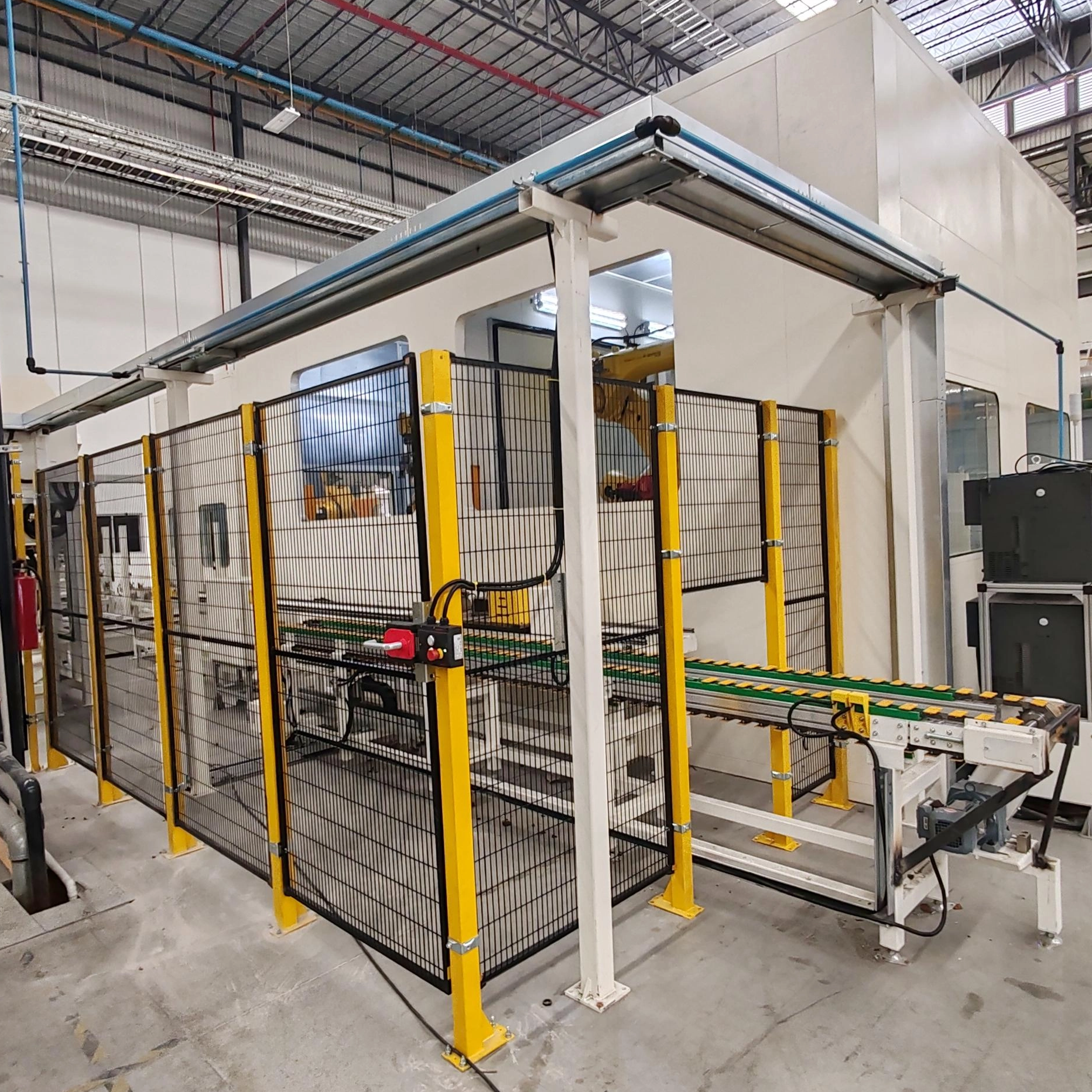
Integrating a Gate Cutting Machine requires careful evaluation of production scalability on the shop floor.
Cycle Time Synchronization: The cutting equipment must operate within the injection molding machine's cycle time. If the degating process takes longer than the molding cycle, a bottleneck forms. Ensure the automated cutter can keep pace with high-speed production.
Footprint and Integration: Evaluate whether end-of-arm tooling (EOAT) or a standalone cutting station fits your floor plan better. EOAT integrates the cutting action directly onto the extraction robot, saving floor space. Standalone stations offer higher cutting forces and easier maintenance access for heavy-duty applications.
Air Supply Stability: Pneumatic cutters require consistent air pressure. Drops in shop air pressure will result in incomplete cuts. Install dedicated regulators for the cutting stations.
Automating the degating process introduces specific mechanical risks that require proactive mitigation strategies.
Risk: Premature blade wear occurs rapidly when processing glass-filled or highly abrasive polymers. Standard steel blades dull quickly, leading to crushed gates and poor cosmetic finishes.
Mitigation: Specify carbide-tipped blades or specialized hardened steel alloys. Implement a routine blade inspection schedule based on cycle counts.
Risk: Micro-cracking often happens when shearing brittle materials like Acrylic or Polystyrene. Cold cutting forces stress into the part, causing delayed failure.
Mitigation: Utilize heated cutting solutions. Heating the blade softens the polymer precisely at the shear point, allowing for a smooth cut without propagating stress fractures.
A frequent error in mold design is failing to account for runner weight and multi-cavity layouts. Engineers sometimes calculate gate size based solely on a single part's volume. This mistake ignores the total flow required through the primary feed system. When you ignore total shot capacity, you create severe pressure imbalances, especially in family molds. The cavities nearest the sprue overpack, while the outer cavities suffer from short shots. Always calculate the total shot volume before sizing the individual gates.
The desire to minimize gate vestige often leads to undersized gates. While a small gate improves cosmetic appearance and reduces trimming time, it severely restricts material flow. Undersized gates cause the melt to freeze prematurely. The molding machine cannot apply sufficient packing pressure through a frozen gate. This trade-off results in short shots, sink marks, and high internal stresses. You must prioritize proper cavity packing over minimal vestige during the initial sizing calculations.
Conversely, excessively large gates delay freeze-off. The molding machine must hold pressure longer to prevent material from flowing back out of the cavity. This extended hold time increases the overall cooling time. Cycle time bloat reduces production yield and drives up part costs. An oversized gate also creates a massive vestige that requires heavy-duty automated cutting equipment. You must find the precise balance where the gate is large enough to pack the part but small enough to freeze quickly.
Designing a gate that optimizes flow but is inaccessible for post-processing creates massive production headaches. Engineers sometimes place gates in recessed areas or complex contours to hide the vestige. However, standard cutting blades cannot reach these locations. This misalignment forces manufacturers to invest in costly custom automation or revert to slow manual trimming. Always consider the physical dimensions of standard cutting blades and nippers when deciding on gate placement and size.
Audit your current mold flow analyses to ensure gate dimensions align with material viscosity and part wall thickness.
Calculate the required cutting forces for your specific polymer and gate size combinations using the cross-sectional area formula.
Request cycle-time demonstrations and test cuts from equipment manufacturers to verify blade geometry and cylinder force.
Standardize blade geometries across your facility to reduce spare parts inventory and simplify maintenance.
A: Calculate edge gate depth as a percentage of the part's nominal wall thickness. For high-flow materials, use 50% to 60%. For high-viscosity materials, use 70% to 90%. The formula is: Gate Depth = Wall Thickness × Material Flow Constant.
A: Determine total shot weight by multiplying the part weight by the number of cavities, then adding the runner weight. Divide this total weight by the specific density of the polymer at processing temperature to find the total shot volume.
A: High-viscosity materials like Polycarbonate resist flow and require larger gate depths to prevent excessive shear heating and pressure loss. Low-viscosity materials like Nylon flow easily and can utilize smaller gates without risking short shots.
A: Manual trimming becomes ergonomically unsafe and inefficient when gate thickness exceeds 2.0mm, especially with rigid or glass-filled polymers. Beyond this threshold, automated cutting machines are required to maintain production speed and part quality.
A: Use the formula: Force = Gate Cross-Sectional Area × Material Tensile Strength. Calculate the area by multiplying gate width by depth. Always add a 20% to 30% safety margin to account for blade wear and minor material variations.
A: Standard steel blades dull rapidly when cutting abrasive glass-filled polymers. To handle these materials efficiently, you must equip the machine with carbide-tipped blades or specialized hardened steel alloys and monitor blade wear closely.
A: A longer gate land length increases frictional resistance, requiring higher injection pressure to push the melt into the cavity. Keep land lengths short (typically 0.5mm to 2.0mm) to minimize pressure drop and prevent premature freeze-off.


