
- All
- Product Name
- Product Keyword
- Product Model
- Product Summary
- Product Description
- Multi Field Search
English
Views: 0 Author: Site Editor Publish Time: 2026-07-29 Origin: Site


Capital equipment procurement in foundry operations carries high stakes. Selecting the right Gravity Die Casting Machine directly dictates long-term production efficiency, part quality, and operational profitability. A misaligned machine choice leads to severe consequences on the foundry floor: high scrap rates due to porosity, excessive maintenance downtime, and bottlenecks in post-processing stages like heat treatment. Procurement managers and manufacturing engineers must navigate complex technical specifications to ensure the equipment matches their production requirements. Choosing an inadequate machine architecture results in dimensional inaccuracies and structural failures in the final cast parts. We use a structured evaluation framework to assess technical specifications, compare machine architectures, and calculate operational capabilities before finalizing a purchase.
Match Architecture to Geometry: The choice between vertical, horizontal, and tilting configurations must be driven by part complexity, metal flow requirements, and the need to minimize turbulence.
Prioritize Mold Compatibility: Accurate assessment of mold size capacity—specifically the distance between tie bars and the maximum die stroke—is non-negotiable for current and future production flexibility.
Control Porosity for Heat Treatment: For parts requiring subsequent heat treatment, selecting machines with advanced flow control (such as tilting mechanisms) is critical to eliminating gas entrapment and pore problems.
Gravity die casting occupies a specific volume niche on the manufacturing floor. It proves highly cost-effective for medium-volume production runs, bridging the gap between low-volume sand casting and ultra-high-volume high-pressure die casting. When evaluating machines, you must define your expected production thresholds clearly. Cycle time expectations directly dictate the necessary level of machine automation and the sophistication of integrated cooling capabilities. Faster cycle times demand robust, automated pouring systems and highly efficient thermal management to maintain mold integrity over consecutive shifts.
Foundry managers often miscalculate the true cycle time by ignoring the solidification window of specific alloys. A machine might physically open and close in ten seconds, but if the aluminum requires three minutes to solidify without tearing, the mechanical speed means nothing. You need to evaluate the machine's ability to integrate with automated ladles and robotic extractors. If the machine lacks the necessary PLC inputs and outputs for this automation, you will rely on manual labor, which introduces variability in pour rates and cycle consistency.
Casting Method | Ideal Volume Range | Tooling Cost | Cycle Time Speed |
|---|---|---|---|
Sand Casting | 1 - 1,000 units | Low | Slow |
Gravity Die Casting | 1,000 - 50,000 units | Medium | Moderate |
High-Pressure Die Casting | 50,000+ units | High | Fast |
The physical dimensions and weight of the final casting determine the required clamping force and structural rigidity of the machine. Heavier, more complex parts exert significant metallostatic pressure during the solidification phase, requiring massive platen stability. If the platens deflect even a fraction of a millimeter under this pressure, the casting will develop flash along the parting line, requiring expensive secondary grinding and fettling operations.
Specific aluminum or brass alloys behave differently during the pour. High-strength aluminum alloys, such as A356, require precise thermal management to ensure uniform cooling and prevent shrinkage defects. Brass alloys pour at much higher temperatures, demanding robust die coatings and superior cooling circuit designs within the machine platens. You must match the machine's thermal capacity to the specific metallurgical demands of your chosen alloy.
Gravity die casting stands out because it utilizes expendable sand cores to produce complex hollow geometries. Machine selection must accommodate these requirements seamlessly. You need to evaluate how the equipment handles core-pulling sequences, whether it supports multiple slide cores, and if it allows for efficient manual or automated sand core placement without extending cycle times unnecessarily.
When casting parts like intake manifolds or pump housings, the sand core must remain perfectly stable during the metal pour. The machine must provide precise locating pins and secure clamping to prevent core shift. If the machine's hydraulics are jerky or inconsistent, the vibration can crack delicate sand cores before the metal even enters the mold, leading to internal sand inclusions and scrapped parts.
The structural rigidity and clamping stability of the machine heavily influence the surface finish and dimensional repeatability of the castings. A machine that flexes under pressure will produce parts with inconsistent dimensions. Ensuring the platens remain perfectly parallel under maximum clamping force is critical for achieving near-net-shape components that require minimal secondary machining.
Guide tie bars and linear bearings play a massive role here. Over time, wear on these components allows the moving platen to sag. When evaluating a machine, look at the diameter of the tie bars and the length of the guide bushings. Heavier, over-engineered guide systems maintain platen parallelism much longer in a harsh foundry environment, directly translating to tighter dimensional tolerances on your castings.
Porosity remains a constant battle in metal casting. Entrapped gas weakens the mechanical properties of the part. For castings that must undergo subsequent heat treatments (like T6 for aluminum), a smooth, turbulence-free metal entry is non-negotiable. If porosity is present, the entrapped gas will expand during the solution heat treatment phase, causing surface blistering and structural failure.
The machine's ability to control metal flow velocity serves as a primary success criterion. Gating design in the mold handles part of this, but the machine's pouring mechanics handle the rest. If the machine forces a turbulent pour, no amount of clever gating will save the part from oxide films and gas entrapment. You need equipment that facilitates a laminar flow of molten metal into the die cavity.
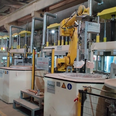
Understanding operational mechanics is essential when choosing between configurations. A Horizontal Gravity Die Casting Unit operates with platens moving horizontally. This configuration often provides better mold accessibility and simplifies complex core-pulling sequences from multiple directions. Operators can easily reach into the open die to place sand cores or clean the mold surface.
Traditional vertical setups are generally more compact but can restrict access for larger molds. In a vertical machine, the parting line is horizontal, which can be advantageous for certain flat, wide components where you want the metal to spread evenly across a large surface area quickly. However, horizontal units excel for long, cylindrical parts or components requiring extensive slide cores on the sides.
When deciding between the two, map out your current and future part geometries. If you anticipate casting tall parts that require deep drafts, a vertical machine might offer better ejection mechanics. If you are casting complex automotive housings with multiple side cores, the horizontal architecture provides the necessary clearance for the hydraulic core pull cylinders.
A Tilting Gravity Die Casting Unit controls the pouring rate via programmable tilt angles. The mold is tilted during the pour, allowing gravity to gently guide the molten metal into the cavity. This metallurgical control significantly reduces turbulence and minimizes oxide inclusions, leading to a drastic reduction in pore problems.
The mechanics involve a robust trunnion system and heavy-duty hydraulic cylinders that rotate the entire clamping unit and mold assembly. The operator or automated ladle pours the metal into a receiving cup while the machine is horizontal. As the machine tilts to a vertical position, the metal flows smoothly down the gating system, pushing air out ahead of it without folding or splashing.
This architecture is justified for safety-critical aerospace brackets, automotive engine blocks, or suspension components where scrap rates must be minimized and mechanical integrity is paramount. The reduction in turbulence directly correlates to higher elongation and tensile strength in the final cast part, making it suitable for rigorous structural applications.
Calculating required platen sizes is the first step in technical evaluation. The distance between tie bars is the most critical limiting factor for mold accommodation; it dictates the maximum physical dimensions of the mold you can load into the machine. You cannot simply look at the platen dimensions; you must measure the clear space between the bars.
You must also carefully review the daylight opening, maximum ejector stroke, and the maximum and minimum die height specifications. If your mold is too thin, the machine won't be able to clamp it. If it's too thick, it won't fit between the open platens. The ejector stroke must be long enough to push the cast part completely clear of the mold cavity, especially for parts with deep ribs or bosses.
Measure the width and height of your largest existing mold.
Add a minimum of 50mm clearance on all sides for safe loading and unloading.
Verify this dimension against the machine's tie bar clearance.
Check the maximum open daylight against the mold thickness plus the required part extraction clearance.
Reliable operation depends on robust hydraulic and automation systems. Evaluate the requirements for hydraulic cylinder precision, proportional valve control, and overall system pressure stability. Inconsistent hydraulic pressure leads to flashing and dimensional variations. You need a hydraulic power pack that can maintain high clamping force even as the metal heats and expands the mold slightly.
The integration of programmable logic controllers (PLCs) is vital for recipe management, precise automated pouring sequences, and synchronized part ejection. Modern PLCs allow you to save specific machine parameters for each mold, including tilt speeds, cooling water duration, and core pull timing. This eliminates operator guesswork during mold changes and ensures repeatable quality across different shifts.
Look for machines utilizing high-quality proportional valves. Standard directional valves simply open and close, causing jerky movements that can damage molds and sand cores. Proportional valves allow for smooth acceleration and deceleration of the platens and tilt mechanisms, extending the life of the machine and the tooling.
Maintaining optimal die temperatures requires integrated water or air cooling circuits. Precise thermal management extends die life by reducing thermal fatigue and heat checking on the mold surface. It also ensures consistent dimensional accuracy across production runs by controlling the solidification rate of the metal.
Machines with advanced, multi-zone cooling controls provide the best outcomes for complex geometries. A thick section of a casting will require aggressive water cooling to solidify at the same time as a thin section. The machine must have multiple independent cooling circuits, controlled by the PLC and triggered by timers or thermocouples embedded in the mold.
Cooling Method | Application | Control Mechanism |
|---|---|---|
Air Cooling | Thin walls, slow cycle times | Timed compressed air blast |
Water Cooling (Continuous) | Heavy sections, high heat loads | Manual flow valves |
Water Cooling (Pulsed) | Precise thermal balancing | PLC-controlled solenoid valves |
There is a significant risk of high initial defect rates while dialing in tilt profiles, cooling times, and coating applications on a new machine. The first few dozen shots will likely be scrap as the mold reaches operating temperature and the operators adjust the PLC timers. To mitigate this, require comprehensive vendor support for the initial runoff on your foundry floor.
Establish clear acceptance criteria based on actual part quality and dimensional accuracy, rather than just verifying that the machine cycles dry. The vendor should stay on-site until the machine produces consecutive, defect-free parts that pass X-ray and dimensional inspection. Document the exact PLC parameters used to achieve this success to create a baseline recipe.
Molten metal handling and hydraulic pinch points present severe hazards. A gravity die casting machine operates with immense clamping forces and handles aluminum at 700 degrees Celsius. Ensure the machine features comprehensive safety guarding, interlocked doors, and light curtains that immediately halt machine movement if an operator breaches the safety zone.
Mitigation relies heavily on the vendor providing rigorous, documented operator training. This training must cover safe operation, emergency stop procedures, manual override functions, and routine maintenance tasks like cleaning the platens and checking hydraulic fluid levels. Never allow untrained personnel to operate or troubleshoot the equipment.
Integrating a new machine with existing robotic ladles, extractors, and conveyor systems can be complex. Communication bottlenecks can halt production. If the machine's PLC cannot talk to the robot's controller, you will face constant faults and downtime. Verify communication protocol compatibility, such as Profinet or EtherNet/IP, before purchase.
Work with your automation integrator early in the procurement process. Provide them with the electrical schematics and PLC logic of the proposed machine to ensure they can write the necessary handshake signals. The machine must be able to signal the robot when the mold is open and clear, and the robot must signal the machine when the part is extracted and it is safe to close.
Selecting the right casting equipment requires balancing geometric capability, metallurgical control, and long-term reliability on the foundry floor. You must evaluate the physical dimensions, the hydraulic power, and the thermal management capabilities to ensure they align with your specific alloy and part requirements.
Measure all current and future molds to establish a hard minimum for tie bar distance and daylight opening.
Determine if your parts require heat treatment; if so, mandate a tilting architecture to eliminate turbulence and porosity.
Audit the machine's PLC and hydraulic valve specifications to ensure smooth, repeatable movements that protect sand cores.
Request physical test casts of your most complex part on the vendor's demo machine before signing the final purchase agreement.
A: The primary advantage is controlled metal flow. It significantly reduces turbulence and minimizes porosity, which is critical for parts requiring high mechanical strength or subsequent heat treatment.
A: Tie bar distance dictates the maximum physical dimensions of the mold that can be loaded. You must measure the widths and heights of your current molds and project future mold sizes to ensure compatibility.
A: Horizontal units are often better suited for parts requiring complex, multi-directional core pulls or specific gating designs due to improved mold accessibility and core-handling capabilities.
A: Gravity die casting offers lower tooling costs and is suitable for low-to-medium production volumes. Crucially, it allows the casting of parts with internal cavities using sand cores, which is difficult or impossible in HPDC.
A: Ongoing upkeep includes hydraulic system maintenance, replacing wear pads and bushings to maintain platen alignment, servicing die cooling circuits, and the regular application of refractory coatings to the molds.
A: Entrapped gas (porosity) expands during heat treatment, causing surface blistering and structural degradation. Turbulence-free casting via tilting or inclined mechanisms is essential to prevent this.


