
- All
- Product Name
- Product Keyword
- Product Model
- Product Summary
- Product Description
- Multi Field Search
English
Views: 0 Author: Site Editor Publish Time: 2026-09-01 Origin: Site


Precision in sand core manufacturing dictates the dimensional accuracy and surface finish of final foundry castings. When a facility experiences inconsistent core density, excessive resin consumption, or incomplete curing, operators often take the blame. However, these issues rarely stem from human error. They are symptoms of degraded, poorly specified, or obsolete machine components failing under the stress of continuous production.
Understanding the exact anatomy of a Cold Box Core Shooter helps you accurately diagnose production bottlenecks. By evaluating the mechanical condition of each subsystem, foundry engineers make informed decisions regarding maintenance schedules and component replacements. Recognizing how individual parts interact allows teams to evaluate OEM versus aftermarket options effectively and justify capital expenditures for targeted upgrades or custom-designed solutions that permanently resolve recurring quality defects.
Shooting Head Integrity: The shooting head and blow plate assembly are the most critical variables for achieving uniform sand compaction and preventing core defects, especially in complex core geometries.
Gas Generation Efficiency: Precision control in the gas generator and purging system directly impacts curing times, amine/catalyst consumption, and environmental compliance, eliminating the risk of incomplete curing.
Wear Part Economics: Proactive evaluation of high-abrasion parts (nozzles, discharge valves, sand magazines) reduces unplanned downtime and lowers overall operational expenses.
Automation & Customization: Retrofitting legacy mechanical systems with modern PLCs, or investing in custom-designed tooling, offers a high-ROI pathway to transforming foundry output without replacing the entire machine.
Mapping the lifecycle of a sand core within the machine reveals a highly synchronized sequence of mechanical and chemical events. Every component in this chain must execute its function with exact timing and force to maintain continuous production. The standard operational sequence follows these distinct phases:
Intake and Staging: A precise mixture of silica sand, resin, and catalyst enters the staging area from the overhead mixer.
Fluidization and Injection: The machine fluidizes and injects this mixture under high pressure into a closed core box cavity.
Chemical Curing: A gas generator introduces a vaporized catalyst to cure the binder, hardening the sand into its final shape.
Purging and Ejection: The machine purges residual gases through an exhaust system and ejects the finished core for handling.
Machine configurations dictate specific component requirements and wear profiles. Semi-automatic core shooters rely on manual intervention for core box loading and unloading. Their safety interlocks, manual clamping mechanisms, and sliding rails experience high physical wear from constant operator interaction. Fully automatic systems operate continuously, placing immense stress on pneumatic valves, limit switches, and automated ejection pins. The continuous duty cycle of automatic machines accelerates the degradation of internal seals and nozzles. You need rigorous predictive maintenance schedules to keep them running efficiently.
A high-performing system meets strict success criteria across all operational phases. Minimal sand bridging in the hopper ensures uninterrupted material flow. Exact volumetric dosing prevents material waste and maintains consistent core weights. Optimal gas dispersion guarantees uniform tensile strength throughout the core. Rigid clamping prevents dimensional distortion during the high-pressure injection phase.
To effectively evaluate and maintain these machines, we divide the architecture into four distinct operational zones:
Sand Preparation and Delivery
Shooting Mechanism
Curing and Gas Control
Tooling and Automation
The mixture hopper serves as the primary receiving and staging environment for the prepared silica sand, resin, and catalyst blend. Its primary function is to maintain the flowability of the mixture while preventing premature curing or separation of the binder from the sand grains. The hopper must hold enough volume to supply continuous shooting cycles without causing the heavy sand mixture to compact under its own weight.
Design variations in the hopper directly impact material flow dynamics. Conical designs are standard but frequently suffer from rat-holing. This happens when sand sticks to the angled walls and only the center column flows downward, leaving stagnant material on the sides that eventually cures and hardens. Cylindrical designs with agitated bottoms or steeper discharge angles provide a more consistent mass flow. They ensure the shooting chamber receives a uniform volume of sand for every cycle.
Evaluating hopper performance requires inspecting the internal surfaces. The silica sand mixture is highly abrasive and chemically sticky. Bare steel walls quickly degrade, leading to severe sand bridging and flow interruptions. Applying internal coatings, such as Teflon or Ultra-High Molecular Weight (UHMW) polyethylene, on all parts in contact with the mixture reduces the friction coefficient. These coatings prevent adhesion, facilitate smooth material transfer, and protect the underlying steel from rapid abrasion.
Controlling the drop of the sand mixture from the hopper into the shooting chamber relies on robust discharge valves. Butterfly valves utilize a rotating disc to open and close the flow path. They offer quick actuation but expose the disc edges to constant abrasion. Pinch valves use a flexible rubber sleeve that compresses to stop flow. They provide a completely unobstructed path when open but require frequent sleeve replacements. Slide gates operate by driving a steel plate across the opening. This effectively cuts through the sand column but jams easily if sand grains infiltrate the guide tracks.
The abrasive nature of silica sand presents severe wear and maintenance risks for all flow control components. As sand flows past valve seals, it acts like sandpaper. It slowly erodes the tolerances required to maintain a pressure-tight seal. When discharge valves fail to seal completely, the subsequent shooting cycle forces compressed air back up into the hopper. This causes pressure leaks and weak core compaction. Utilizing hardened steel plates or polyurethane-lined valve bodies extends component life and maintains the pressure integrity of the shooting sequence.
Routine maintenance for discharge valves should include:
Weekly visual inspections of the rubber sleeves in pinch valves for signs of cracking or thinning.
Monthly calibration of the pneumatic actuators driving the slide gates to ensure full closure.
Quarterly replacement of the perimeter seals on butterfly valves to prevent blow-by.
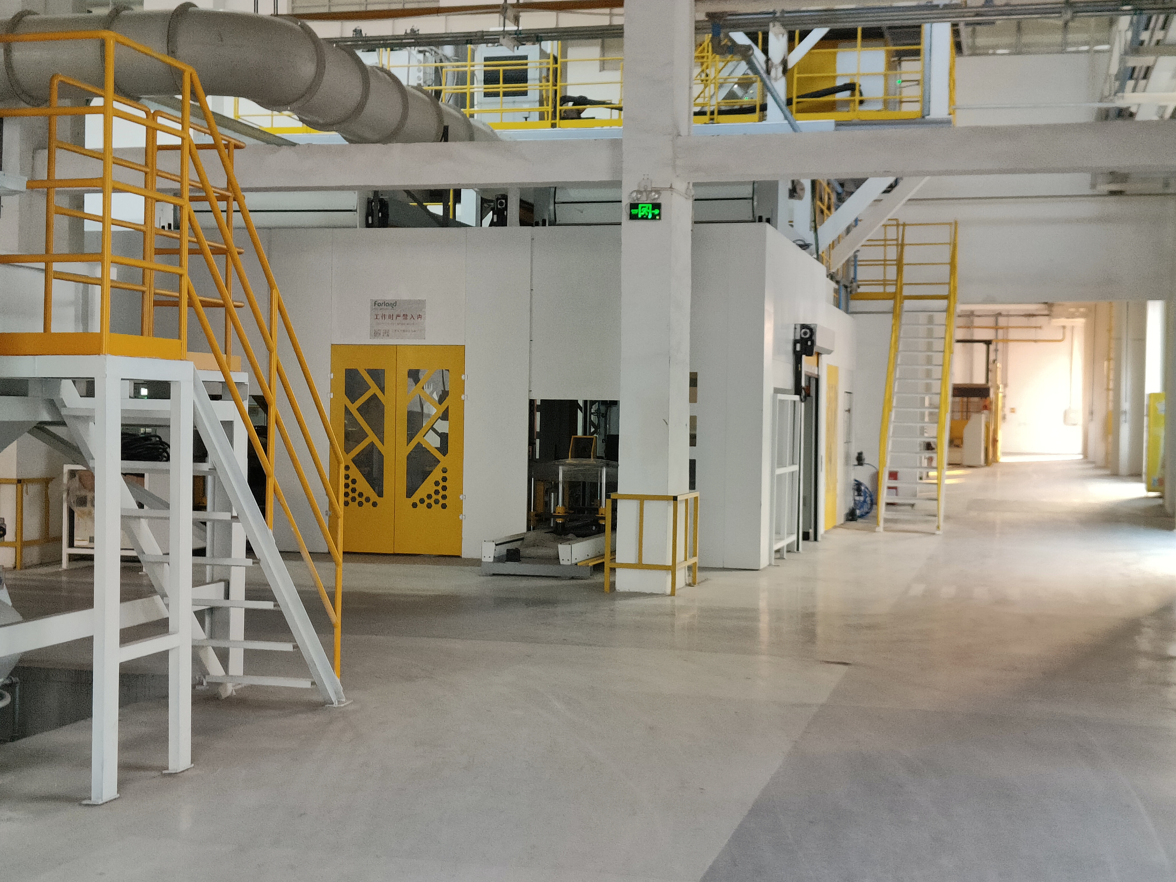
The shooting head is the mechanical heart of the machine. Its core function is to instantly pressurize the staged sand mixture and inject it into the tooling cavity. When the shoot valve opens, a massive volume of compressed air fluidizes the sand, carrying it through the blow plate and into the core box. The speed and uniformity of this pressurization dictate the kinetic energy transferred to the sand grains.
Shooting head volume capacity and exhaust valve response times directly influence core density and structural integrity. If the head volume is too small for the core box, the sand will not pack tightly. This results in soft cores that crumble during handling. Conversely, the exhaust valves must vent residual pressure immediately after the cavity fills. Sluggish exhaust valves leave the core box pressurized for too long, forcing sand into the parting lines and creating flash.
Operators must balance conceptual trade-offs between shooting pressure and equipment wear. High shooting pressure, typically between 3 to 6 bar, achieves superior compaction. You need this to drive sand into deep ribs and complex geometries. However, excessive pressure accelerates wear on the core box surfaces and increases the risk of sand blow-by at the parting lines. Optimizing the shooting head involves tuning the pressure to the exact minimum required for full compaction, thereby preserving tooling life.
Blow plates serve as the interface between the shooting head and the core box. Technical specifications for blow plates require exact hole patterning and precise nozzle alignment to match the injection ports of the tooling. The plate must withstand the immense downward force of the clamping system while resisting the abrasive blast of fluidized sand.
Custom-designed blow plates and specialized nozzle configurations resolve specific technical challenges when manufacturing highly complex cores. Standard uniform nozzle placement often fails to fill intricate sections. By mapping larger nozzles to thick core sections and smaller, directed nozzles to thin or restricted areas, engineers control the sand flow velocity and prevent voids in the final product.
Material selection for injection nozzles determines their operational lifespan and sealing capability.
Nozzle Material | Wear Resistance | Sealing Capability | Best Application |
|---|---|---|---|
Standard Steel | Moderate | Poor (Rigid) | Basic, high-volume cores with flat parting lines. |
Hardened Alloy | Excellent | Poor (Rigid) | Highly abrasive sand mixtures, long production runs. |
Polyurethane/Rubber-Tipped | Low to Moderate | Excellent (Flexible) | Complex tooling requiring a perfect pressure seal to prevent blow-by. |
The implementation realities of nozzle maintenance heavily impact production economics. Running worn nozzles leads to poor edge definition on the cores, localized soft spots, and significantly increased scrap rates. Establishing a strict replacement frequency based on cycle counts rather than visual failure prevents these quality drops and maintains consistent foundry output.
The cold box curing process relies on the precise chemical handling of a catalyst, typically an amine gas or sulfur dioxide (SO2). The gas generator unit receives the liquid catalyst, vaporizes it completely, and doses it into the core box. Liquid catalyst must be heated and mixed with a carrier gas, usually compressed air or nitrogen, to create a uniform vapor that penetrates the compacted sand matrix.
Evaluating gas generators requires assessing their ability to deliver precise, repeatable catalyst volumes while maintaining consistent vaporization temperatures. If the temperature drops, the catalyst remains in a liquid droplet state. These droplets cause localized over-curing, leaving heavy resin deposits on the tooling, while other areas of the core remain uncured and weak.
Advanced gas dispersion technology solves the common technical challenge of incomplete curing in intricate core sections. By utilizing proportional valves and mass flow controllers, modern generators adjust the gas concentration dynamically during the curing cycle. This ensures the vapor reaches the deepest recesses of the core box before the carrier gas channels through the path of least resistance.
An efficient gas generator acts as a primary value-influencing factor for the entire foundry. Amines and specialized catalysts are expensive consumables. By optimizing the vaporization and dosing process, a high-performance generator drastically reduces catalyst consumption. It eliminates the environmental hazard of over-gassing and shortens the overall cycle time by accelerating the curing phase.
Following the gas injection, the machine initiates a heated air purge cycle. The process mechanics involve forcing high-volume, low-pressure heated air through the same blow plate nozzles. This purge pushes the active catalyst completely through the sand matrix, ensuring a full chemical reaction with the resin, and then evacuates all residual gases from the core box. The purge air is typically heated between 80°C and 100°C to prevent the vaporized amine from condensing back into a liquid inside the tooling.
The exhaust system functions as an essential environmental and safety component. Unreacted amine gas is highly toxic and corrosive. The exhaust pipelines capture the purged gases and direct them to an acid scrubber system. The scrubber neutralizes the chemicals before venting to the atmosphere. Maintaining leak-proof, corrosion-resistant piping protects operators from exposure and ensures the facility meets strict environmental compliance standards.
The base frame provides the structural foundation for the entire Cold Box Core Shooter. Structural requirements dictate a high-rigidity heavy steel construction capable of absorbing the severe kinetic energy generated during the shooting process. If the frame flexes even a fraction of a millimeter under pressure, the core box separates, resulting in scrap cores and equipment damage.
Hydraulic and pneumatic pipelines form the nervous system of the machine. High-pressure hoses, steel manifolds, and heavy-duty fittings maintain exact machine timing and operational safety. A sudden loss of hydraulic pressure due to a blown fitting during the shoot cycle causes catastrophic tooling failure. Regular inspection of these pipelines for wear, heat degradation, and secure routing is mandatory.
Clamping mechanisms secure the core box halves together during the high-pressure shoot. Hydraulic cylinders offer massive, unyielding clamping force. This makes them ideal for large or complex tooling that requires absolute rigidity. Pneumatic cylinders provide faster actuation speeds for smaller core boxes but compress slightly under extreme shooting pressures. Sufficient clamping force is vital. Inadequate pressure allows the sand mixture to force the tooling apart, generating flash that requires expensive manual grinding to remove.
Tooling integration defines how the machine interfaces with the core box. The machine platens must accommodate custom foundry designs, utilizing standardized mounting grids or quick-change magnetic systems. Accurate alignment between the machine's blow plate and the core box intake ports ensures smooth sand transfer without turbulence or pressure loss.
Proper venting within the core box is equally important. Vents allow the carrier gas and displaced air to escape while trapping the sand grains. Clogged vents create backpressure, preventing sand from filling the cavity and leading to soft, unusable cores. Operators must inspect and clean these vents regularly.
Once the core is cured, ejection systems safely remove it from the tooling. Mechanical or pneumatic ejector pins push the core out of the cavity. These pins must actuate simultaneously and with balanced force. Uneven ejection pressure causes the rigid sand core to fracture or suffer dimensional distortion, rendering it useless for the final casting process.
The modernization of foundry equipment has driven a complete shift from outdated relay-logic panels to advanced Programmable Logic Controllers (PLCs) paired with intuitive HMI touchscreens. Modern PLCs process thousands of inputs per second. They allow for micro-second adjustments to valve timing, pressure regulation, and safety interlocks. This digital control eliminates the mechanical lag associated with older electrical systems.
Sensor integration provides the closed-loop feedback necessary for precision manufacturing. Pressure transducers monitor the exact force inside the shooting head. Limit switches verify the absolute position of the clamping cylinders. Temperature sensors ensure the gas generator maintains optimal vaporization heat. If any sensor detects a deviation from the programmed parameters, the PLC halts the cycle before a defective core is produced.
Evaluating the scalability of these control systems involves assessing their connectivity. Modern PLCs easily integrate into broader Manufacturing Execution Systems (MES). This integration allows foundry managers to track data in real-time, monitor cycle-time deviations, integrate with casting simulation software, and implement predictive maintenance schedules based on actual machine cycles rather than calendar estimates.
Diagnosing part failures requires a structured framework based on performance-to-outcome metrics. By analyzing specific core defects, maintenance teams trace the issue back to the failing component. For example, consistently soft cores typically indicate low shooting pressure caused by worn exhaust valves or a degraded shooting head seal. The presence of flash along the parting lines points directly to insufficient clamping force or a flexing base frame. Localized uncured sand indicates poor gas dispersion, requiring an inspection of the gas generator and purge pipelines.
When troubleshooting machine performance, follow this diagnostic sequence:
Identify the Defect: Isolate whether the issue is dimensional (flash, warping) or structural (soft spots, crumbling).
Check Pneumatic Supply: Verify that the main airline delivers consistent pressure without drops during the shoot cycle.
Inspect Seals: Examine the blow plate O-rings and discharge valve sleeves for abrasive wear.
Verify Catalyst Flow: Ensure the gas generator maintains the correct vaporization temperature and that the mass flow controllers register the proper dosage.
When replacing components, foundries must objectively weigh their sourcing options. The following table outlines the comparative advantages of OEM, Aftermarket, and Custom parts:
Part Sourcing Strategy | Primary Advantages | Ideal Application Scenarios | Implementation Considerations |
|---|---|---|---|
OEM Components | Guaranteed tolerances, exact fit, preserves machine warranty, predictable lifespan. | Control systems (PLCs, sensors), high-pressure hydraulic manifolds, gas generators. | Higher initial purchase price; may have longer lead times depending on manufacturer location. |
Aftermarket Wear Parts | Cost-effective, readily available, standard dimensions. | High-turnover consumables like standard steel nozzles, rubber pinch valve sleeves, basic seals. | Variable quality control; requires rigorous incoming inspection to ensure dimensional accuracy. |
Custom-Engineered Parts | Solves specific geometry issues, optimizes sand flow, reduces scrap on difficult jobs. | Specialized blow plates, directed nozzle arrays, modified sand magazines for unique resins. | High initial engineering cost; requires close collaboration with tooling designers and flow simulation. |
Major component overhauls carry inherent implementation risks. Replacing a gas generator or upgrading a PLC panel requires significant machine downtime. To mitigate these risks, foundries should plan phased upgrade strategies during scheduled maintenance shutdowns. Pre-assembling and bench-testing custom blow plates or pneumatic manifolds before taking the machine offline ensures a rapid return to full production capacity.
Conduct a comprehensive machine audit focusing on the wear patterns of blow plates, nozzles, and discharge valves to establish a baseline for replacements.
Log cycle-time deviations and pressure drops daily to identify failing hydraulic or pneumatic seals before they cause catastrophic downtime.
Calibrate the gas generator and purge systems monthly to prevent liquid catalyst carryover and reduce expensive chemical consumption.
Consult with tooling engineers to specify custom blow plates and directed nozzles for core boxes currently experiencing high scrap rates.
A: The shooting head pressurizes the staged sand and resin mixture using a high-volume blast of compressed air. It fluidizes the sand and injects it through the blow plate into the core box, providing the kinetic energy required to densely pack the sand into complex tooling geometries.
A: Replacement frequency depends entirely on cycle counts and the abrasiveness of the sand mixture. Standard steel nozzles require replacement every few weeks in high-production environments, while hardened alloys last longer. Replace them immediately when internal wear alters sand flow or causes poor edge definition on the cores.
A: Incomplete curing is typically caused by poor gas dispersion, low vaporization temperatures in the gas generator, or inadequate purging pressure. If the catalyst remains in a liquid state or the carrier gas channels through the path of least resistance, deep or intricate core sections will not harden.
A: Hardened steel or specialized alloys are best for resisting the severe abrasion of silica sand. Polyurethane or rubber-tipped nozzles are often used because they create a superior, leak-proof seal against the core box, though they degrade faster from chemical exposure to curing gases.
A: A highly efficient gas generator completely vaporizes the catalyst and doses it precisely. This ensures uniform core strength, prevents sticky resin buildup on the tooling, drastically reduces the consumption of expensive amine gases, and shortens the overall production cycle time.
A: Yes. Retrofitting legacy machines with modern PLCs and HMI touchscreens is a common and highly effective upgrade. It replaces unreliable mechanical relays with digital controls, allowing for precise sensor integration, better pressure regulation, and real-time cycle monitoring without purchasing a completely new machine.
A: The high-pressure injection of sand generates massive kinetic energy that attempts to force the core box halves apart. Sufficient hydraulic or pneumatic clamping force holds the tooling completely closed. Inadequate clamping allows sand to escape the cavity, creating flash that ruins the core.


