
- All
- Product Name
- Product Keyword
- Product Model
- Product Summary
- Product Description
- Multi Field Search
English
Views: 0 Author: Site Editor Publish Time: 2026-09-10 Origin: Site


High-volume metal manufacturing requires a strict balance between dimensional precision, repeatability, and unit efficiency. Selecting the wrong casting method, ignoring part size limitations, or misaligning material properties with production machinery leads to accelerated tooling wear, high defect rates, and inverted unit economics. Operating without a clear technical strategy quickly turns a high-speed manufacturing advantage into a logistical liability.
Establish a framework for evaluating whether implementing or outsourcing a dedicated casting operation is the optimal route for your specific component specifications, volume thresholds, and performance requirements. Engineers and production managers must align metallurgical constraints with mechanical capabilities to ensure long-term viability. A properly configured Die Casting Production Line transforms raw alloys into complex, net-shape components at speeds unmatched by traditional machining, provided the initial setup parameters are strictly controlled.
Volume Dictates Viability: High initial tooling and machinery costs mean die casting is typically only economically viable for production runs exceeding 10,000 units.
Process Follows Material: The choice between hot-chamber and cold-chamber die casting is strictly dictated by the melting point of the chosen alloy (e.g., zinc vs. aluminum).
Tooling Lifespan Impacts ROI: Material selection directly influences the degradation of reusable steel molds; lower-melting-point alloys extend die life and reduce long-term operational costs.
Complexity and Precision: Die casting excels at producing small to medium-sized, geometrically complex metal parts with tight tolerances, operating on a "negative shape" principle similar to plastic injection molding.
Defect Mitigation is Critical: Success relies on precise thermal management and pressure control to prevent common structural failures like porosity and shrinkage.
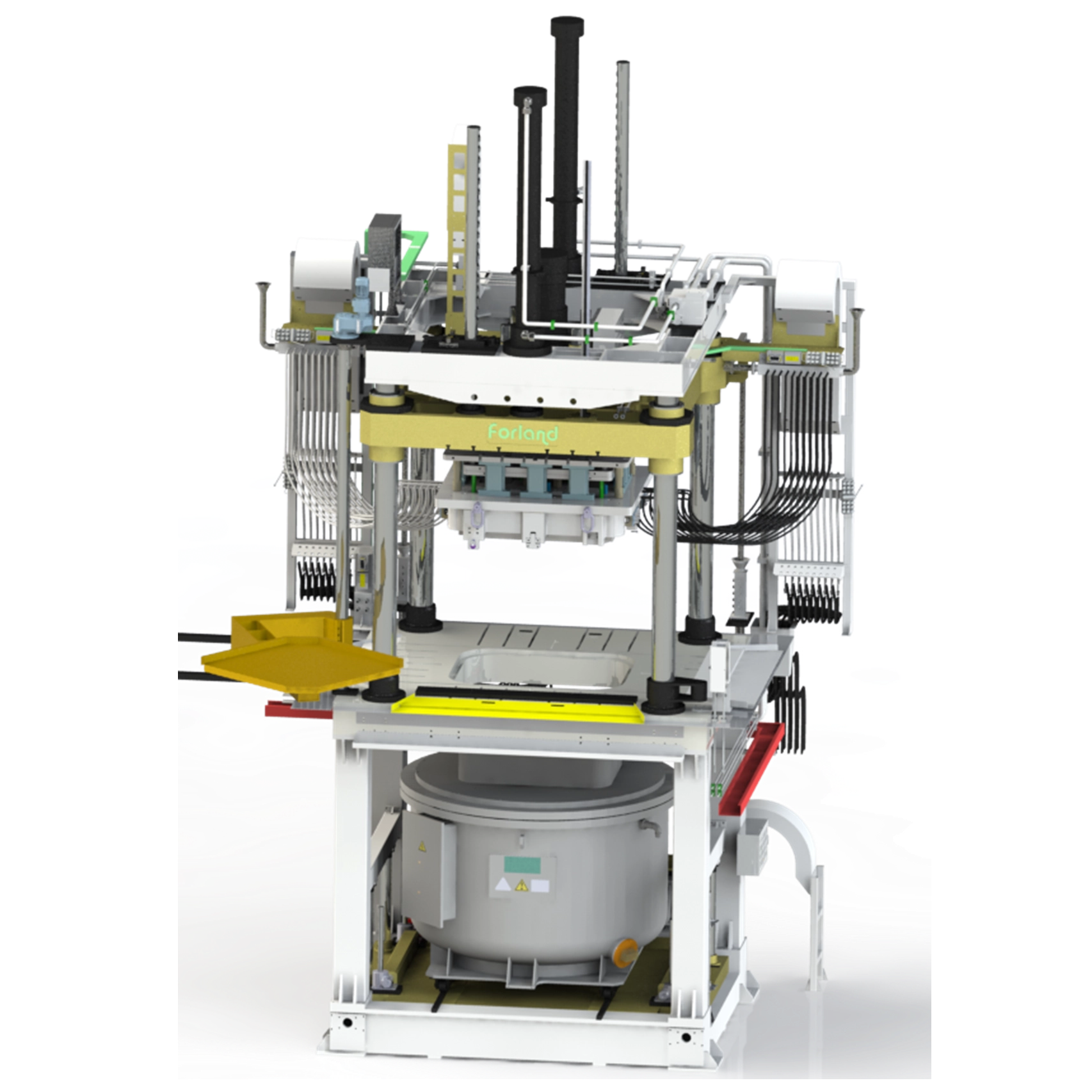
A modern casting facility requires a substantial physical footprint engineered to handle extreme heat, high hydraulic pressures, and rapid mechanical movements. The central infrastructure consists of a melting furnace, an injection mechanism, and the die clamping system. Holding furnaces maintain the alloy at precise casting temperatures, preventing premature solidification before the metal reaches the shot sleeve. The clamping unit must exert massive tonnage—often ranging from 400 to 4,000 tons—to keep the die halves sealed against the explosive force of the injected molten metal. Heavy steel tie bars guide the moving platen, ensuring perfect alignment during every cycle. Surrounding this core machinery are cooling towers, ventilation systems, and automated extraction robotics that handle the finalized castings.
The molds form the heart of the operation. Machined primarily from premium hardened H13 tool steel, these dies consist of two primary halves: the cover die (fixed to the stationary platen) and the ejector die (mounted to the moving platen). Tooling must withstand brutal thermal cycling, absorbing heat from molten metal and rapidly dissipating it through internal cooling channels. Dimensional accuracy relies entirely on the structural integrity of this steel. Engineers design these molds with complex internal geometries, incorporating sliders, lifters, and core pins to create undercuts and lateral features. The quality of the tool steel directly dictates the maximum number of shots the mold can endure before heat checking or catastrophic failure occurs.
The mechanical sequence of a single casting shot occurs in fractions of a second. The process follows a strict, repeatable sequence to ensure part consistency:
Die Clamping: Hydraulic cylinders drive the moving platen forward, locking the ejector die against the cover die under maximum tonnage.
Metal Transfer: An automated ladle or integrated pump transfers a precise volume of molten metal from the holding furnace into the injection system.
High-Speed Injection: The plunger advances, forcing molten metal into the die cavity at extreme pressures, typically ranging from 1,500 to 25,000 psi. This high velocity ensures the metal fills thin-walled sections before solidifying.
Solidification and Dwelling: The system holds hydraulic pressure as the part cools, feeding additional metal into the cavity to compensate for natural volumetric shrinkage.
Ejection and Lubrication: The clamping unit opens, mechanical ejector pins push the solidified part out of the mold, and automated sprayers apply a specialized water-based die lubricant to cool the steel and facilitate the next ejection.
Scaling a casting operation requires minimizing human intervention. Automated ladles transfer exact volumes of molten metal from the holding furnace to the shot sleeve, ensuring volumetric consistency and reducing the size of the residual biscuit. Extraction robots remove the hot casting, verify its structural integrity via optical sensors, and transfer it to quenching tanks. Secondary operations are integrated directly into the workflow. Automated trim presses shear off the runners, gates, and flash, while inline shot blasting stations unify the surface finish. Real-time monitoring systems track injection speed, die temperature, and hydraulic pressure, automatically flagging anomalies that could lead to structural defects.
In hot chamber casting, the injection mechanism sits permanently submerged within the holding furnace's molten metal bath. A hydraulically actuated plunger forces the metal through a gooseneck-shaped channel directly into the die cavity. This direct immersion eliminates the need to transfer metal manually or mechanically between cycles. Cycle times are exceptionally fast, often yielding hundreds of shots per hour. Because the metal remains shielded within the furnace environment until injection, oxidation is virtually eliminated. However, this process is strictly limited to low-melting-point alloys like zinc, magnesium, and lead. Exposing the submerged steel plunger and gooseneck to high-melting-point metals like aluminum would rapidly dissolve and destroy the injection system.
Cold chamber casting separates the melting furnace from the injection system. For each cycle, an automated ladle transfers a precise amount of molten metal from the furnace into an unheated, horizontal shot sleeve. A hydraulic plunger then drives the metal from the sleeve into the die. This physical separation allows the machinery to process high-melting-point alloys, primarily aluminum, brass, and copper, without destroying the injection components. The trade-off is efficiency. The transfer process inherently slows down cycle times and exposes the molten metal to ambient air, increasing the risk of oxidation and heat loss before injection. Plunger tips in cold chamber machines require constant lubrication and frequent replacement due to the abrasive nature of aluminum.
Standard high-pressure processes occasionally trap air, leading to internal voids. Vacuum die casting solves this by drawing a hard vacuum on the die cavity milliseconds before injection, evacuating ambient air and drastically reducing gas porosity. This upgrade is mandatory for components requiring post-casting heat treatment or welding, as trapped gas would expand and blister the part under high heat. Squeeze casting represents another variation, injecting metal at lower velocities but applying massive pressure during solidification. This method produces near-forging quality components with high structural integrity, ideal for critical load-bearing applications like automotive suspension knuckles.
Process Type | Compatible Alloys | Cycle Speed | Primary Advantage | Primary Limitation |
|---|---|---|---|---|
Hot Chamber | Zinc, Magnesium, Lead | Very Fast | Minimal oxidation, high throughput | Cannot process aluminum or brass |
Cold Chamber | Aluminum, Brass, Copper | Moderate | Handles high-melting-point metals | Slower cycles, higher oxidation risk |
Vacuum Assisted | Aluminum, Magnesium | Moderate | Eliminates gas porosity | Requires complex die sealing systems |
Squeeze Casting | Aluminum Alloys | Slow | Heat-treatable, high-strength parts | Lower production volume capacity |
Aluminum dominates the casting industry due to its exceptional dimensional stability, natural corrosion resistance, and high thermal and electrical conductivity. Alloys like A380 offer the best combination of casting ease and mechanical properties, making them the default choice for most structural components. A383 is specified when complex geometries require better die-filling characteristics due to its higher silicon content. Because aluminum requires cold-chamber processing, its higher melting point (around 1,200°F or 650°C) accelerates die wear compared to zinc. While aluminum naturally resists corrosion, aesthetic applications often require secondary surface treatments like anodizing, powder coating, or specialized chemical conversion coatings to achieve the final desired finish.
Zinc alloys, particularly the Zamak series (Zamak 3, 5, and 7), offer unparalleled ductility and impact strength. Zinc's high fluidity allows engineers to cast extremely thin walls and intricate details that would fail in aluminum. Its low melting point (around 730°F or 390°C) allows for hot-chamber processing, resulting in rapid cycle times and extending tooling life significantly—often yielding over one million shots per die. Zinc is highly compatible with electroplating, making it ideal for decorative hardware and automotive interior components. The primary trade-off is density; zinc parts are significantly heavier than aluminum or magnesium, and the material is subject to creep when exposed to continuous elevated temperatures.
Magnesium provides the highest strength-to-weight ratio of any commonly cast metal. It is approximately 30% lighter than aluminum, making it the premier choice for weight-critical aerospace and automotive applications. Alloy AZ91D offers excellent machinability and dampening capacity, absorbing vibrations effectively. Magnesium can be cast in both hot and cold chambers, though hot chamber is preferred for thin-walled parts. The drawbacks involve material handling. Molten magnesium poses severe flammability risks, requiring specialized inert gas shielding over the melting furnace to prevent atmospheric ignition. Facilities must implement strict safety protocols when machining magnesium parts to manage combustible dust.
Selecting the right alloy requires mapping material properties directly to functional outcomes. If the primary goal is lightweighting a handheld device, magnesium is the definitive choice. If the component operates in a high-heat engine compartment, aluminum provides the necessary thermal stability. For decorative consumer hardware requiring a flawless chrome-plated finish, zinc delivers the best surface adhesion and impact resistance. Engineers must balance these functional requirements against production line longevity; specifying aluminum for a part that could functionally be made of zinc will unnecessarily accelerate tooling degradation and increase long-term maintenance cycles.
Casting is optimized for small to medium-sized parts with consistent, relatively thin walls. Ideal wall thicknesses range from 1.5mm to 3mm for aluminum, and can go as thin as 0.5mm for zinc. Uniform wall thickness is critical; transitioning abruptly from a thick section to a thin section causes uneven cooling rates. The thinner section solidifies first, restricting the flow of molten metal to the thicker section, which leads to shrinkage porosity and internal voids. If thick sections are unavoidable, they must be cored out to maintain a uniform material volume. Keeping walls thin ensures rapid, uniform cooling, which accelerates cycle times and improves the mechanical properties of the dense outer skin.
Draft refers to the slight taper applied to vertical walls parallel to the direction of die opening. This taper is non-negotiable. Without sufficient draft, the cooling metal shrinks and locks tightly onto the steel mold cores. Attempting to eject a part without draft results in galling, severe part distortion, and broken ejector pins. Standard draft requirements vary by material and wall depth. Zinc typically requires the least draft (around 0.5 degrees), while aluminum requires more (typically 1 to 2 degrees per inch of depth). Internal features like holes and pockets require greater draft angles than external walls because the metal shrinks inward onto the core pins during solidification.
Sharp internal corners are the enemy of structural integrity. They create severe stress concentrations where the part is highly susceptible to cracking under load. Furthermore, sharp corners disrupt the flow of molten metal, causing turbulence and trapped air. Applying generous fillets (rounded internal corners) and radii (rounded external corners) smooths metal flow and distributes mechanical stress evenly. When a part requires additional strength, simply thickening the wall is counterproductive. Instead, engineers use strategic ribbing. Ribs add immense structural rigidity and bending stiffness without increasing the overall wall thickness, maintaining rapid cooling cycles and preventing shrinkage defects.
While casting produces near-net-shape parts with excellent tolerances, certain critical features—like bearing press-fits, sealing surfaces, or threaded holes—require post-casting CNC machining. DFM requires leaving a specific amount of excess material on these features to accommodate the machining pass. This allowance is typically kept between 0.5mm and 1.0mm. Leaving too much material forces the CNC machine to cut through the dense, rapidly chilled outer skin of the casting and into the softer, potentially porous internal core, which compromises the integrity of the machined feature. Precise allowances ensure the cutting tool only removes the necessary surface layer while maintaining the part's structural integrity.
The transportation sector relies heavily on factory mass production of lightweight structural components. Engine cylinder blocks, transmission housings, and structural brackets are universally cast. The push for electric vehicles has accelerated the demand for large-scale aluminum and magnesium casting to offset heavy battery weights. These components require high structural integrity, precise fluid routing channels, and the ability to dissipate heat rapidly. The process allows automotive manufacturers to consolidate dozens of stamped and welded steel parts into single, complex cast nodes, drastically reducing assembly line complexity and overall vehicle weight.
Modern electronics demand rigid, lightweight enclosures that provide thermal management and electromagnetic interference (EMI) shielding. Laptops, smartphones, and telecommunications base stations utilize cast magnesium and aluminum housings. The process allows for the integration of intricate internal features—like motherboard mounting standoffs, heat sink fins, and snap-fit locking mechanisms—directly into the primary chassis. The tight tolerances achieved out of the mold minimize the need for secondary machining, while the metallic structure naturally shields sensitive internal components from external radio frequency interference without requiring secondary conductive coatings.
Specifying a dedicated casting operation is justified when specific technical and commercial thresholds are met. The primary criteria include production volumes exceeding 10,000 units, the requirement for complex internal cavities that cannot be efficiently CNC machined, and the need for specific metallic properties (like thermal conductivity or EMI shielding) that plastic injection molding cannot provide. When a design requires thin walls, complex 3D topographies, and high mechanical strength, casting outperforms sand casting (which lacks precision) and CNC machining (which is too slow and wastes material at high volumes).
Deploying a casting operation requires massive upfront capital. High-pressure machinery commands significant investment, scaling with the required clamping tonnage. A 400-ton machine requires a smaller footprint and less infrastructure than a 3,000-ton machine required for automotive structural nodes. Beyond the press, facilities must invest in holding furnaces, automated ladles, robotic extractors, and quenching systems. The custom hardened-steel tooling represents the most variable CapEx. A single multi-cavity mold engineered with complex sliders and thermal management channels requires hundreds of hours of precision CNC machining and electrical discharge machining (EDM), representing a major financial commitment before a single part is produced.
Running the equipment generates continuous operational expenses. Energy consumption is the largest factor; maintaining holding furnaces at 1,200°F for aluminum requires constant natural gas or electrical power. Routine maintenance on hydraulic systems, replacing worn shot sleeves, and replenishing die lubricants add to daily operating costs. Post-processing also drives OpEx. Every cast part requires trimming to remove runners, gates, and overflow wells. Depending on the aesthetic requirements, secondary operations like shot blasting, vibratory deburring, or chemical conversion coatings require dedicated labor and consumables.
The economic viability of casting relies on amortizing the high tooling investment over a massive production volume. If a custom mold requires heavy engineering hours and the production run is only 1,000 parts, the tooling allocation per part is prohibitively high. However, if the run is 100,000 parts, the tooling allocation per unit becomes negligible. Engineers calculate the break-even point by comparing the high upfront investment and low unit production of casting against the low upfront investment and high unit production of CNC machining. Once volume crosses the 5,000 to 10,000 unit threshold, casting almost universally becomes the more economical choice.
When evaluating alternatives, metal casting sits between plastic injection molding and sand casting. If material substitution is viable (e.g., a structural bracket can be made of high-strength polymer), injection molding offers lower tooling investments and faster cycle times. However, plastics fail in high-heat or EMI-shielding applications. Compared to sand casting, high-pressure die casting requires vastly more expensive tooling but delivers superior surface finishes, tighter tolerances, and eliminates the need for heavy post-machining. Sand casting remains economically superior only for extremely low volumes or massive parts that exceed the tonnage limits of high-pressure machines.
Design choices heavily influence the final unit economics. Part consolidation is the most effective cost-reduction strategy. Designing one complex cast part to replace an assembly of five stamped, welded, and bolted components eliminates assembly labor, reduces inventory tracking, and offsets the initial tooling investment. Conversely, over-tolerancing drives production expenses up. Specifying aerospace-grade tolerances on non-critical features forces the toolmaker to tighten mold clearances and mandates extensive secondary CNC machining, destroying the inherent unit advantages of the casting process.
Porosity is the most common and destructive defect in metal casting. It occurs when ambient air in the die cavity or gases from vaporized die lubricants become trapped within the turbulent flow of injected metal. These trapped gases form internal voids, compromising structural strength and causing blisters during heat treatment. Mitigation requires rigorous fluid dynamics control. Engineers use mold-flow simulation software to optimize gating designs, ensuring a smooth, laminar metal flow. Incorporating overflow wells at the edges of the cavity gives trapped air a place to escape. For critical components, upgrading to vacuum-assisted casting is the definitive solution.
The extreme thermal cycling of rapid heating during injection and rapid cooling during lubrication causes the surface of the H13 tool steel to expand and contract violently. Over thousands of cycles, this fatigue manifests as a network of microscopic surface cracks known as heat checking. These cracks transfer onto the cast part as raised metallic fins. Mitigating thermal fatigue requires precise control over die temperatures using internal cooling channels carrying pressurized water or thermal oil. Establishing strict maintenance schedules for die stress-relieving—removing the mold and tempering it in an oven—resets the steel's internal stresses and prolongs tooling life.
As molten metal transitions to a solid state, it inherently shrinks. If the part cools unevenly, different sections shrink at different rates, causing the entire component to warp and lose dimensional accuracy. Thick sections that cool slower than thin sections will develop internal shrinkage voids as the outer shell pulls material away from the molten core. Mitigation relies heavily on DFM—maintaining uniform wall thickness—and precise thermal management within the die. Strategically placed cooling lines must extract heat faster from thicker regions to ensure the entire part solidifies simultaneously.
Visual defects often indicate underlying process instability. Cold shuts occur when two streams of molten metal meet but fail to fuse completely because the metal cooled too rapidly, leaving a visible seam and a structural weak point. Flow marks appear as concentric ridges on the surface, indicating poor injection velocity. Blistering happens when trapped gas expands near the surface. Preventing these defects requires continuous calibration of the injection speed, maintaining optimal holding furnace temperatures, and ensuring the die lubricant is applied evenly without pooling in deep cavities.
Integrating a production line into regulated industries like automotive or aerospace demands stringent quality assurance protocols. Visual inspection is insufficient. Facilities must deploy real-time X-ray inspection to detect internal porosity without destroying the part. Coordinate Measuring Machines (CMM) verify that complex geometries and machined features meet strict dimensional tolerances. Maintaining ISO 9001 or automotive IATF 16949 certifications requires documenting every process variable—injection pressure, metal temperature, cooling rates—ensuring total traceability for every batch of components produced.
Finalize a strict Design for Manufacturability (DFM) review to ensure uniform wall thicknesses and appropriate draft angles before finalizing CAD models.
Conduct comprehensive mold-flow simulations to identify potential porosity risks and optimize gating locations before cutting steel.
Request detailed tooling and piece-production quotes from certified manufacturing partners to accurately calculate your volume break-even point.
Define exact secondary machining and surface finishing requirements to establish total unit economics.
A: The high initial investment for hardened steel tooling and machinery setup generally requires a minimum production volume of 5,000 to 10,000 units to achieve a viable return on investment. Below this threshold, CNC machining or sand casting is usually more economical.
A: Tooling investment scales directly with part complexity, cavity count, and mold size. A simple single-cavity mold requires less capital, while complex multi-cavity dies featuring automated sliders, intricate cooling channels, and premium H13 tool steel demand a higher initial expenditure based on engineering hours.
A: Both processes inject material into a reusable mold under pressure. Injection molding uses thermoplastic polymers for lightweight, low-heat applications. Die casting uses molten metals like aluminum, zinc, and magnesium for components requiring high mechanical strength, thermal resistance, and electrical conductivity.
A: No. Ferrous metals like steel and iron have melting points that exceed the thermal limits of standard H13 tool steel molds. Attempting to cast them would melt and destroy the reusable die. Steel and iron require sand casting or investment casting.
A: Tooling lifespan depends heavily on the cast alloy. Aluminum molds typically last 100,000 to 150,000 shots due to high melting temperatures causing thermal fatigue. Zinc molds, operating at lower temperatures, can easily exceed one million shots with proper maintenance.
A: Porosity is caused by ambient air trapped during high-speed injection or uneven cooling causing internal shrinkage voids. It is prevented by optimizing gating design via mold-flow simulation, utilizing overflow wells, maintaining uniform wall thickness, and employing vacuum-assisted casting.
A: Draft angles ensure clean part ejection without galling. Zinc typically requires 0.5 degrees of draft per inch of depth. Aluminum and magnesium require more, typically 1 to 2 degrees per inch. Internal features always require slightly larger draft angles than external walls.


