
- All
- Product Name
- Product Keyword
- Product Model
- Product Summary
- Product Description
- Multi Field Search
English
Views: 0 Author: Site Editor Publish Time: 2026-09-11 Origin: Site


High-volume metal part manufacturing requires a strict balance between dimensional precision, cycle speed, and unit repeatability. Selecting the wrong casting method or misconfiguring a manufacturing setup leads to excessive tooling wear, unacceptable porosity rates, and compromised unit economics. Understanding the exact mechanics, equipment requirements, and material constraints of a modern Die Casting Production Line—most commonly referred to in the industry as High-Pressure Die Casting (HPDC)—determines whether this process aligns with your production volume and structural requirements. We will break down the core components, operational differences, and design constraints necessary to successfully implement high-pressure metal casting on the factory floor.
Volume dictates viability: The high initial capital expenditure (CapEx) for hardened steel molds requires high production volumes (typically 10,000+ units) to achieve a competitive return on investment.
Material dictates machinery: The choice between aluminum, zinc, and magnesium strictly determines whether a hot-chamber or cold-chamber production line is required.
Defect mitigation is systemic: Managing porosity and flash requires precise control over injection pressure, cooling rates, and automated trimming within the production line.
Automation drives scalability: Modern die casting relies heavily on robotics for ladling, extraction, and die lubrication to maintain consistent cycle times and reduce thermal variance.
High-pressure casting operations start at the melt deck. Raw metal ingots and recycled scrap transform into a molten state inside industrial furnaces. Furnace specifications vary based on the alloy, but operators must maintain optimal viscosity at all times. If the metal runs too cold, it solidifies prematurely in the mold and causes cold shuts. If it runs too hot, it accelerates die wear and increases the risk of gas entrapment.
Central melting furnaces feed smaller holding furnaces located directly at the casting cell. Before the molten metal reaches the injection mechanism, operators execute rigorous fluxing and degassing procedures. Fluxing agents separate impurities, bringing dross to the surface for manual or automated skimming. For alloys like aluminum, rotary degassing introduces argon or nitrogen gas to remove dissolved hydrogen. Skipping material preparation guarantees structural defects in the final casted component.
The defining feature of this manufacturing process is the extreme pressure used to force molten metal into a steel mold cavity. Pressures range from 1,500 to 25,000 psi. This high-velocity injection ensures the metal completely fills intricate geometries and thin wall sections before solidification begins.
Machine tonnage ratings dictate the physical capabilities of the press. Ranging from 400-ton machines for small components to massive 4,000+ ton presses used in automotive mega-casting, this rating refers to the clamping force applied to keep the die halves closed during injection. If the injection pressure exceeds the clamping force, the die blows open. This causes severe safety hazards and excessive flash on the part.
Shot speed control relies on a highly calibrated hydraulic system. The injection profile generally follows three distinct phases:
Slow Approach Phase: The plunger moves past the pour hole slowly to push metal into the runner system without trapping ambient air.
Fast Fill Phase: The hydraulic accumulator fires, pushing the plunger at high velocity to pack the cavity in milliseconds before the metal freezes.
Intensification Phase: The machine applies maximum hydraulic pressure at the end of the stroke to feed additional metal into the cavity as the part shrinks during cooling.
Once the cavity fills, thermal management dictates the cycle time. Dies feature complex internal cooling channels circulating water or specialized thermal oils. This extracts heat rapidly and uniformly. Uneven cooling leads to warped parts, internal stress, and localized shrinkage porosity. Maintenance teams must regularly descale these cooling lines to maintain proper flow rates.
After solidification, the machine opens. Automated ejection systems push the part out of the cavity. Ejector pins must apply even force across the component to prevent distortion. Proper draft angles in the part design allow the casting to release from the steel mold without galling or dragging.
Post-casting operations immediately follow extraction. The part passes through a quench tank to rapidly drop its temperature. Next, a hydraulic trim press shears away the runner system, overflows, and excess flash. Finally, vibratory deburring or shot blasting prepares the surface for final inspection or secondary finishing.
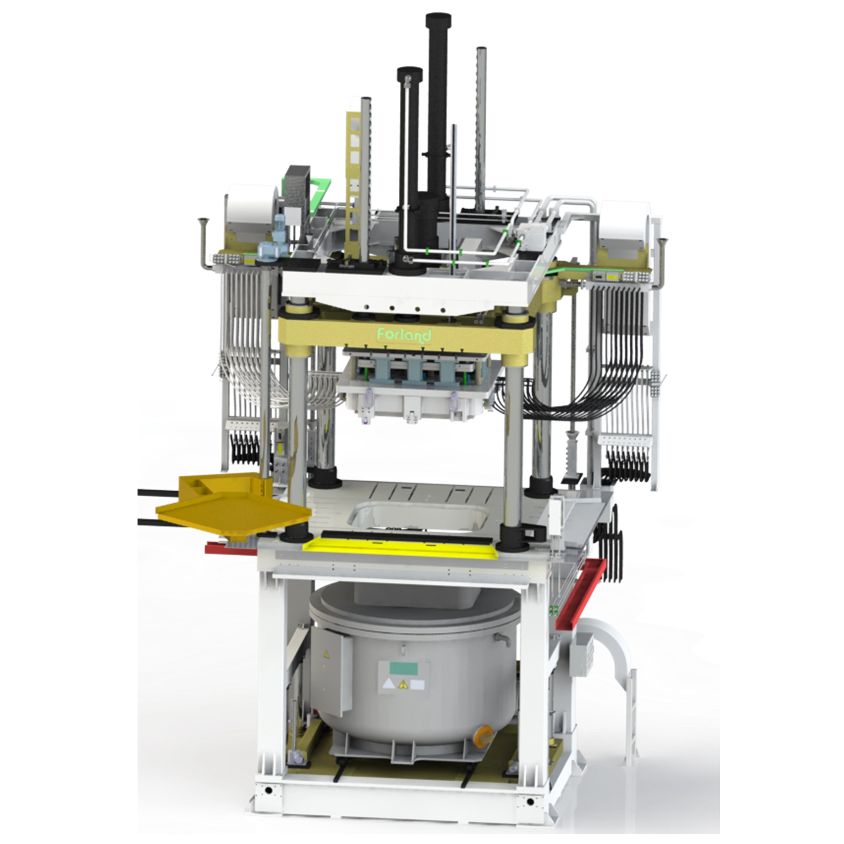
In a hot chamber setup, the injection mechanism—specifically the gooseneck and plunger—sits submerged directly inside the holding furnace's molten metal bath. When the plunger retracts, metal flows naturally into the chamber. When it fires, the metal travels directly up the gooseneck and into the die.
Manufacturers use this system exclusively for low-melting-point alloys such as zinc, magnesium, and lead. Higher-melting-point metals would rapidly degrade and dissolve the submerged steel components. Hot chamber machines offer distinct advantages in speed. Because the metal does not require transfer via a ladle, cycle times are exceptionally fast. Operators often achieve hundreds of shots per hour. The submerged system minimizes the metal's exposure to ambient air, reducing oxidation and resulting in highly precise, dense components.
Cold chamber systems separate the melting furnace from the injection mechanism. Molten metal transports—usually by an automated robotic ladle—from a holding furnace into an unheated cylindrical shot sleeve attached to the machine. A hydraulic plunger then advances through the sleeve, pushing the metal into the die.
This configuration is mandatory for high-melting-point alloys like aluminum, brass, and copper. These metals would quickly destroy the submerged pumping mechanisms of a hot chamber machine. The primary trade-off is cycle speed. The additional step of ladling metal into the cold sleeve extends the cycle time. It also introduces a brief window where the molten metal contacts ambient air. This requires precise ladling automation and shot profile control to maintain throughput and minimize oxide inclusions.
System Feature | Hot Chamber Production Line | Cold Chamber Production Line |
|---|---|---|
Injection Mechanism | Submerged in molten metal bath | External cold sleeve, metal ladled in |
Compatible Alloys | Zinc, Magnesium, Lead | Aluminum, Brass, Copper |
Cycle Speed | Very Fast (up to hundreds/hour) | Slower (due to ladling step) |
Oxidation Risk | Low (metal drawn from below surface) | Moderate (exposed during ladling) |
Tooling Wear | Lower thermal stress on machine parts | High thermal stress on sleeve and tip |
The ability to produce complex, near-net-shape parts rapidly makes this process a staple of modern manufacturing. In the automotive and heavy machinery sectors, engineers utilize it to manufacture durable components such as engine cylinder blocks, transmission cases, and structural brackets. The shift toward electric vehicles has further increased demand for lightweight aluminum battery housings and structural nodes.
Consumer electronics and telecommunications rely heavily on this method for producing lightweight, heat-dissipating enclosures. Magnesium and aluminum are favored for laptops, smartphone frames, and 5G base station heat sinks due to their excellent thermal conductivity and EMI shielding properties.
Historically, the optimal range for this manufacturing method has been small to medium-sized parts weighing between a few ounces and fifty pounds. However, the recent advent of mega-casting—utilizing presses exceeding 6,000 tons—actively expands these physical limits. Automakers now cast entire vehicle underbodies as single components.
Financial viability hinges entirely on production volume. The hardened H13 tool steel dies required to withstand extreme pressures and thermal shock are expensive to design and machine. Calculating the breakeven point involves amortizing this high initial tooling cost against the exceptionally low per-part production cost.
When compared to CNC machining, casting becomes economically superior once volumes cross the 5,000 to 10,000 unit threshold. CNC machining offers zero tooling costs but high per-part times and massive material waste. Conversely, sand casting offers lower tooling costs but yields poor surface finishes, lower dimensional precision, and slower cycle times. This makes sand casting unsuitable for high-volume, tight-tolerance applications.
High-pressure injection yields exceptional dimensional stability. Standard achievable tolerances typically sit at ±0.002 inches for small dimensions, with high repeatability across production runs spanning hundreds of thousands of shots. This precision drastically reduces or entirely eliminates the need for secondary machining operations.
The as-cast surface finish is generally smooth and uniform, directly reflecting the polish of the steel die. Parts emerge ready for a variety of secondary surface treatments. Depending on the alloy, components can be easily plated, powder-coated, painted, or anodized to enhance corrosion resistance or cosmetic appeal.
Alloy Type | Standard Linear Tolerance (per inch) | Minimum Wall Thickness | Typical Surface Finish (Ra) |
|---|---|---|---|
Aluminum (A380) | ± 0.002" | 0.060" - 0.080" | 32 - 63 µin |
Zinc (Zamak 3) | ± 0.001" | 0.025" - 0.040" | 16 - 32 µin |
Magnesium (AZ91D) | ± 0.002" | 0.040" - 0.060" | 32 - 63 µin |
Successful execution requires strict adherence to Design for Manufacturability (DFM) principles. Wall thickness must remain as uniform as possible. Thick sections cool slower than thin sections, leading to localized shrinkage porosity and warped geometries. Instead of designing solid thick masses, engineers must utilize ribbing and coring to maintain structural integrity while keeping walls thin.
Draft angles are mandatory. Vertical walls parallel to the direction of the die opening must taper to allow the part to eject smoothly. Undercuts require complex mechanical slides within the tool. Slides increase tooling costs and introduce potential maintenance failure points on the production floor.
Gas entrapment is the most persistent challenge in high-pressure metal injection. Because metal forces into the cavity at extreme velocities, turbulent flow traps ambient air and vaporized die lubricants before they escape through the vents. This results in gas porosity, which compromises the mechanical strength of the part.
Mitigation strategies require highly engineered tooling. Advanced gating designs ensure a smooth, calculated metal flow. Overflow wells machined outside the main part cavity catch the first, coldest wave of metal and trapped gases. For critical structural components, facilities implement vacuum die casting technology. This system evacuates air from the mold cavity mere milliseconds before injection. It drastically reduces internal porosity and allows the final parts to undergo heat treatment or welding.
Defect Type | Primary Cause | Factory Floor Mitigation Strategy |
|---|---|---|
Gas Porosity | Trapped air or vaporized lubricant during fast fill. | Add vacuum systems, optimize venting, reduce spray volume. |
Shrinkage Porosity | Uneven cooling in thick wall sections. | Increase intensification pressure, add cooling lines, core out thick areas. |
Cold Shuts | Metal solidifies before completely filling the cavity. | Increase melt temperature, increase fast shot speed, open gate thickness. |
Flash | Injection pressure exceeds machine clamping force. | Move to a higher tonnage press, clean die mating surfaces. |
The extreme environment inside the press takes a heavy toll on the steel molds. Thermal fatigue, caused by the rapid heating from molten metal followed by rapid cooling from internal water lines, eventually causes heat checking. Heat checking appears as a network of fine surface cracks on the die face. Washout occurs when high-velocity metal physically erodes the steel near the gate. Soldering happens when molten aluminum chemically bonds to the steel die surface.
Preventative maintenance protocols maximize tool life. Tooling engineers must periodically remove dies, stress-relieve them in an oven, and repolish the cavities. During production, automated spray manifolds apply specialized water-based or oil-based die lubricants between every shot. This lubricant provides a thermal barrier, aids in part release, and prevents soldering.
Modern casting facilities utilize heavy automation to remove human error and maintain strict thermal consistency. A typical casting cell integrates a central PLC that communicates with the press, the furnace, and multiple robots.
Six-axis robots handle automated ladling. They ensure the exact same volume of metal transfers at the exact same speed every cycle. Automated sprayers apply precise amounts of lubricant to specific areas of the die. Extraction robots remove the hot part, verify its integrity via sensors, and place it into the quench tank or trim press. This level of automation stabilizes the thermal rhythm of the die, directly improving overall equipment effectiveness (OEE) and reducing scrap rates.
Establishing an in-house casting facility requires massive capital expenditure. Beyond the cost of the presses, furnaces, and robotics, the facility infrastructure requires heavy modification. Operations need high-voltage electrical drops, massive cooling water towers, specialized ventilation for furnace exhaust, and strict environmental compliance systems for handling lubricants and dross.
For most OEMs, leveraging a dedicated contract manufacturer shifts this burden from CapEx to OpEx. By utilizing an established supplier's existing infrastructure, companies avoid the steep learning curve of metallurgical management and machine maintenance. You pay only for the tooling and the piece price of the finished components.
When selecting a contract manufacturing partner, physical equipment is only half the equation. Robust quality management systems dictate the reliability of the supply chain. Evaluate potential partners on their certifications, such as ISO 9001 for general manufacturing or IATF 16949 for automotive applications.
Advanced suppliers utilize real-time process monitoring capabilities. Systems monitor the plunger speed and pressure on every single shot, automatically rejecting parts that fall outside established parameters. Strict material traceability ensures that every finished component traces back to the specific batch of raw ingot and the exact date and time of casting.
Initiate a Design for Manufacturability (DFM) review with a tooling engineer to identify thick sections and potential failure points.
Finalize all draft angles and radii on your CAD models to ensure clean ejection and longer tool life.
Determine your exact annual volume requirements to accurately calculate tooling amortization.
Request a detailed tooling and piece-price quote from certified suppliers, ensuring they specify their porosity mitigation strategies.
A: High-pressure die casting forces metal into the mold at extreme speeds and pressures, making it ideal for thin walls and rapid cycle times. Low-pressure casting uses gentle pressure (usually under 15 psi) to slowly fill the mold from the bottom up. This results in denser parts with significantly less porosity, but operates at much slower cycle times.
A: Tool life is dictated by the metal being cast and the resulting thermal stress. Aluminum molds typically last between 100,000 to 150,000 shots due to high injection temperatures. Zinc molds experience much lower thermal shock and can easily last for over 1 million shots before requiring replacement.
A: Standard high-pressure parts generally cannot be welded or heat-treated. The process naturally traps small amounts of gas inside the metal. If the part is heated to welding or heat-treatment temperatures, this trapped gas expands, causing the metal surface to blister and fail. Vacuum casting technology is required if these secondary processes are necessary.
A: Aluminum is the most common material due to its excellent strength-to-weight ratio and thermal conductivity. Zinc is highly favored for applications requiring extreme precision, thin walls, and long tool life. Magnesium is utilized when ultra-lightweight characteristics are the primary design requirement.
A: In a cold chamber machine, molten metal is transferred via a ladle from a holding furnace into an unheated horizontal shot sleeve. A hydraulic plunger then rapidly advances, forcing the metal into the die cavity. This method is mandatory for high-melting-point alloys like aluminum that would otherwise dissolve submerged pumping mechanisms.
A: Porosity stems from two main sources. Gas porosity occurs when ambient air or vaporized lubricants are trapped in the molten metal during the high-speed injection phase. Shrinkage porosity happens when thicker sections of the metal cool and contract slower than the surrounding thin areas, creating internal voids.
A: Designing, CNC machining, heat-treating, and testing a hardened steel mold is a time-intensive process. Lead times typically range between 8 to 12 weeks. This timeframe depends heavily on the geometric complexity of the part, the inclusion of moving slides, and the specific manufacturer's current production backlog.


